Hi guys,
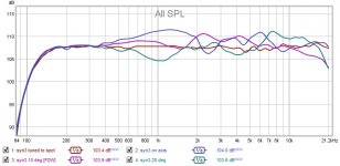
Yes, that was a result of using averaged measurements at 0,10,&20 degrees for tuning, and then measuring the tuning result based on the averages at 10 degree.
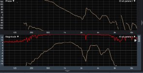
Below is an All-Spl graph that shows that previous trace along with measurements at on-axis and 20 degrees.
See all the crazy waffling around 1k ?
The orange-ish trace that is nice and flat, is a tuning to 10 deg using only the 10 deg measurement. But that tuning makes the pattern wobble even worse at on-axis and 20 deg.
Completely agree that the trouble is.."with conical horns we can build" .....
Too funny about Keele's change of career
I guess the thing with usual-build synergies, is that the problems with straight sided conicals are offset by the benefits of acoustic co-loading.
I think I'll go back to proto2 and add secondary flares...
Uhg though, it's already so damn big I can't move it without taking the drivers out...
Yes, that was a result of using averaged measurements at 0,10,&20 degrees for tuning, and then measuring the tuning result based on the averages at 10 degree.
Below is an All-Spl graph that shows that previous trace along with measurements at on-axis and 20 degrees.
See all the crazy waffling around 1k ?
The orange-ish trace that is nice and flat, is a tuning to 10 deg using only the 10 deg measurement. But that tuning makes the pattern wobble even worse at on-axis and 20 deg.
Completely agree that the trouble is.."with conical horns we can build" .....
Too funny about Keele's change of career
I guess the thing with usual-build synergies, is that the problems with straight sided conicals are offset by the benefits of acoustic co-loading.
I think I'll go back to proto2 and add secondary flares...
Uhg though, it's already so damn big I can't move it without taking the drivers out...
Attachments
Mark,I guess the thing with usual-build synergies, is that the problems with straight sided conicals are offset by the benefits of acoustic co-loading.
I think I'll go back to proto2 and add secondary flares...
Uhg though, it's already so damn big I can't move it without taking the drivers out...
I'd say the advantages of the usual-build multi-entry dual section conical horn are primarily in cost and providing a virtual single point source, while the problems are generally ignored, as room and placement/deployment problems generally are so much worse as to make them seem small by comparison.
Of the 10 design criteria I outlined for my SynTripP cabinet, only #9:
...working in smaller venues (sometimes without additional set up help) and advancing arthritis in my left wrist (getting old sucks) require compact size and light weight, which made achieving the above criteria far more challenging.
was not done better by PM's DIY, less than a year later.
As mentioned before, the BMS 4594HE on a RCF HF950 has measurably better polar response than any of the basic "Keele break" straight sided two-part conical horn designs. It also appears to be measurably smoother, requiring less equalization to remove peaks and dips.
Not sure what your design criteria are, but it might be time to empty the conicals and cut your losses ;^).
Cheers,
Art
Yep Art, I have to give it to your SynTripP for being one heck of a fine practical solution.
You kind of warned me a while back when I started a thread called "Feasible Synergy Attempt" (i think), that a synergy might not offer much over the PM's.
That's kinda what helped steer me to some line array experiments instead of then tacking a synergy.
But I'm happy to be finding out for myself now. If I totally crap out, I'm going to schedule a visit to the nearest Danley dealer to hear what I may or may not, be missing.
I like the RCF HF950, but the 60 deg version using the XT1464 sounds a little better i think.
I'll post the 4594he without horn, and on the 1464, in the same 0, 10, 20 deg fashion as previous, just for comparison and a sanity check against the conical.
Saga continues...real progress today !
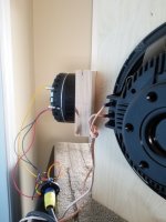
I started by just measuring the 4594he all by itself, no horn.....like Art suggested earlier.
and damn, looked very much like when on the 60x60 and 60x40 horns...not much difference...not good !!!
I'm like yikes, better check this on the XT1464. Which checks out very nicely, just like I'm accustomed to measuring.
So I'm getting really suspect of the simple conical horn hookup with the CD.
Decide to try to replicate the xt1464 for the first inch and half, and try to mate that to the 60x60 horn.
Took two 3/4" pieces of BB and contoured them to match the xt1464 as best I could.
Made transition plates so to speak.
Had to cut the apex of the horn down..BWaslo's killer spreadsheet told me how much to chop off when I changed the square opening size to match 1464 with room to round out corners.
It works, no more pattern flip flop. No more wtf is wrong with what I'm hearing...
It was only a quickie attempt, more careful matching has to help. I'd like to go to maybe 2.25 inches of matching the 1464, but the horn walls using 12mm BB are probably too thin to allow roundover matching.
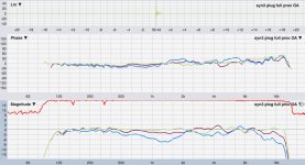
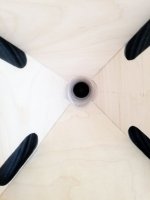
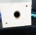
Here's one place going straight to 12"s at 500Hz helps...gives room for the transition plates.
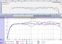
Anyway, picts and a quick meas below. Light green OA, red 10deg, blue 20.
I started by just measuring the 4594he all by itself, no horn.....like Art suggested earlier.
and damn, looked very much like when on the 60x60 and 60x40 horns...not much difference...not good !!!
I'm like yikes, better check this on the XT1464. Which checks out very nicely, just like I'm accustomed to measuring.
So I'm getting really suspect of the simple conical horn hookup with the CD.
Decide to try to replicate the xt1464 for the first inch and half, and try to mate that to the 60x60 horn.
Took two 3/4" pieces of BB and contoured them to match the xt1464 as best I could.
Made transition plates so to speak.
Had to cut the apex of the horn down..BWaslo's killer spreadsheet told me how much to chop off when I changed the square opening size to match 1464 with room to round out corners.
It works, no more pattern flip flop. No more wtf is wrong with what I'm hearing...
It was only a quickie attempt, more careful matching has to help. I'd like to go to maybe 2.25 inches of matching the 1464, but the horn walls using 12mm BB are probably too thin to allow roundover matching.
Here's one place going straight to 12"s at 500Hz helps...gives room for the transition plates.
Anyway, picts and a quick meas below. Light green OA, red 10deg, blue 20.
Attachments
Hi guys, thx for replies,
@ bwaslo, Yes, a FIR filter for each driver. It starts with embedded IIR eqs to smooth the driver's response and phase.
Then adds linear phase crossovers, and the FIR generator tries to match mag and phase to the target crossover curves.
Summation becomes simple flight-time delay adjustment.
It sounds very nice, although I have still some midrange issues with the 12"s to sort out.
Interference at 173 and 346 Hz....don't know what to think yet.
I'm just happy to finally feel like the HF section is solved, and be moving on the the mids.
@nc535, cheering is appreciated I'd love to play with a 3D printer. Gonna search BWaslo's posts for what he did...
@freddi, I wish I knew. I read him say something about the little foam triangles, but have no idea where he put them or why.
@ bwaslo, Yes, a FIR filter for each driver. It starts with embedded IIR eqs to smooth the driver's response and phase.
Then adds linear phase crossovers, and the FIR generator tries to match mag and phase to the target crossover curves.
Summation becomes simple flight-time delay adjustment.
It sounds very nice, although I have still some midrange issues with the 12"s to sort out.
Interference at 173 and 346 Hz....don't know what to think yet.
I'm just happy to finally feel like the HF section is solved, and be moving on the the mids.
@nc535, cheering is appreciated
I'd love to play with a 3D printer. Gonna search BWaslo's posts for what he did...@freddi, I wish I knew. I read him say something about the little foam triangles, but have no idea where he put them or why.
Mark,I started by just measuring the 4594he all by itself, no horn.....like Art suggested earlier.
and damn, looked very much like when on the 60x60 and 60x40 horns...not much difference...not good !!!
I'm like yikes, better check this on the XT1464. Which checks out very nicely, just like I'm accustomed to measuring.
Made transition plates so to speak.
It works, no more pattern flip flop. No more wtf is wrong with what I'm hearing...
It appears to me that your change of vertical resolution and from log to octave has done more to reduce "pattern flip flop" than the transition plates ;^).
The transition plate measurements still show as much as +3 dB at 10 degree off between 2.5 to 5kHz compared to on axis, if anything, a bit worse. It's possible adding a secondary horn break will help the 1.25kHz "waist banding" seen in both the before and after throat plate transitions. Speaking of which, the XT1464 horn profile on their spec sheet looks to reduce the throat to only about 1/2 of the driver entrance, while yours seems nearly 1.4" wide throughout- what do you measure each restriction to be?
It is much easier to look for polar response problems if the on axis response is equalised flat- then one simply looks for deviations in off-axis reduction at each interval, ideally being uniformly -6dB at the initial conical wall angle.
Also, 5 degree increments are helpful, a lot of junk can hide at -5 and -15, and measuring to at least 5 degrees outside the nominal pattern yields important information.
Cheers,
Art
Attachments
@mark100
Nice project
What delay are your FIR Filters introducing at the moment?
Thx Sabblelbackle, about 43ms. (4096taps at 48kHz, impulse centered)
I don't think that is so much a tuning dilemma as a horn issue. I think you made a good choice in that 10 degrees off axis should work well as the center of a listening window. There would be little to complain about in the primary seat even if you didn't keep your head still.
Try a shroud slipping over the front of the horn to implement a secondary flare, as Art Welter did on SynTripP, and things should get better, at least at 1 khz and below. Or try other kinds of mouth treatments. A naked single flare horn mouth, not even baffled, is worst case as I found out to my chagrin.
How did you do the round to rectangular conversion and subsequently smooth the throat? There might be some HF improvements available there.
I'd think that this will help. A secondary flare like the Synergies from Danley (and most others, like Art Welter) have. Easy to test, but yes, it will make the whole setup larger.
Mark,
It appears to me that your change of vertical resolution and from log to octave has done more to reduce "pattern flip flop" than the transition plates ;^). The transition plate measurements still show as much as +3 dB at 10 degree off between 2.5 to 5kHz compared to on axis, if anything, a bit worse. It's possible adding a secondary horn break will help the 1.25kHz "waist banding" seen in both the before and after throat plate transitions. Speaking of which, the XT1464 horn profile on their spec sheet looks to reduce the throat to only about 1/2 of the driver entrance, while yours seems nearly 1.4" wide throughout- what do you measure each restriction to be?
It is much easier to look for polar response problems if the on axis response is equalised flat- then one simply looks for deviations in off-axis reduction at each interval, ideally being uniformly -6dB at the initial conical wall angle. Also, 5 degree increments are helpful, a lot of junk can hide at -5 and -15, and measuring to at least 5 degrees outside the nominal pattern yields important information.
Cheers, Art
Hey Art, decade, octave, 1/3rd octave.... they're all log, eh?
Just a bit different log scaling, one of the hazards with going back and forth between REW and Smaart I guess...I'm still in the proto-exploratory stage, will get to 5 deg work (and verticals) when I move back to the larger horn and do careful transition matching.
Maybe the bit of measurement I showed doesn't look like much of an improvement to you, but it was a nice step forward to both my eyes and ears. The measurements were just a quick on-axis optimization to see how some polars look.... something i couldn't even attempt to do before using OA as the optimazation base...
Lot's of work left to do with better transition matching and processing tradeoffs.
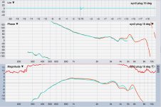
Below is a set of raw HF traces before the transition plate, and second after. Red = OA Aqua = 10 deg
With the plate, measurements between +/- 10 degs are essentially the same as OA. And the dip above 2kHz definitely reduced. To me,it was a nice improvement.
Not sure which xt1464 spec sheet you're looking at, but any throat reduction is an illusion. It expands throughout. I made a stack of 1/4 discs that I could set in the horn when facing up, and measure diameter with calipers, as i went towards the mouth stacking 1/4" at a time. It expanded fairly evenly at +1/8" diameter per 1/4" throat distance for the first inch of throat, ending at 2 3/16" dia at 1.5". So a 2 3/16" round to square match job into the horn...
Attachments
Last edited:
I'd think that this will help. A secondary flare like the Synergies from Danley (and most others, like Art Welter) have. Easy to test, but yes, it will make the whole setup larger.
Very much agree.
In my methodical step by step, build and measure way, I've wanted to get the primary flare working as well as possible before adding the secondary.
I did try adding some flares to the smaller 60x60 when spitballing anything and everything, looking for change/impact. Convinced me to stick with the primary until it got more livable. Too many variables for my meager mellon to juggle !
Drop me a PM, I can send you the STL if you want to print it (needs a 12"x12" print bed). I never made the horn in question completely (put boards on one, but never even added drivers). I was going for a gigantic 5' tall speaker but after working out the stub design realized that I don't have, and will never have, space to put a pair of those into nor even a good place to store them. Same basic arrangement as with the larger "3D printed" waveguide speakers I made, so I expect the results would be similar at least before the LF cutoff frequencies.I'd love to play with a 3D printer. Gonna search BWaslo's posts for what he did...
An early assembly test -- I got the edge-meeting angles wrong on the wood panels (dumb math error), but the idea still works.

This is the final version (two printed, never tested, still sitting on a shelf in the basement)

Attachments
Last edited:
A secondary expansion actually makes the horn smaller. The outer dimensions of the secondary part (assuming the angles are about the right amounts) are what determine the low frequency directivity limit. They reduce waistbanding (by the simple expedient of wider angle for the part that affects low frequencies), but you get to the horiz and vert dimensions faster (with less depth). But it does make the wood cutting and assembly trickier
what did those little foam triangles do to the response of Tom's early Unity horns?
They significantly reduced to the depth of the on axis dip at 4KHz. They were a trapezium, not a triangle. You can see some pictures of them on my webpage.
Last edited:
This is the final version (two printed, never tested, still sitting on a shelf in the basement)
Thank you for your kind STL offer!!!
That looks like an awesome way of beginning/making the prime component of a synergy box. Final version looks incredible. Out of curiosity, for what size CD, and cone drivers, did you make the final version? And what horiz and vertical pattern were you after?I totally hear you about a place to put and then store what we we build. I had to buy a 16ft trailer to handle extra storage for all the boxes I've built over the last 3-4 years....bigger boxes cause I'm into hi-fi PA... and damn trailer is getting full
A secondary expansion actually makes the horn smaller. The outer dimensions of the secondary part (assuming the angles are about the right amounts) are what determine the low frequency directivity limit. They reduce waistbanding (by the simple expedient of wider angle for the part that affects low frequencies), but you get to the horiz and vert dimensions faster (with less depth). But it does make the wood cutting and assembly trickier
Thx again. So it sounds like the secondary flare is more about lower frequency control, than what's going on say above 1kHz?
I'm hoping to add the secondary flares out of detachable foamboard in a construction manner similar to what Thijs666 did. Art's dixie cup. Otherwise, it looks like it will get impossibly heavy (and too awkward to store)
They significantly reduced to the depth of the on axis dip at 4KHz. They were a trapezium, not a triangle. You can see some pictures of them on my webpage.
Many thanks!! Your projects look super !
Can you give some details on the trapezium pieces? Dimensions? It looks like they are on the secondary flares, without going further in the horn? What are they made of, looks like maybe heavy felt?
Sorry for all the questions...yours is the first info i've seen about this...
Out of curiosity, for what size CD, and cone drivers, did you make the final version?
And what horiz and vertical pattern were you after?
That was for a 1"D tweeter driver (like DNA360 or DE250 it was cloned from), mids were the Celestion sealed back TF0410MR . I was going to use Eminence 2512 for woofers (mounted on the boards). Exit angles of the stub are 90 and 65 degrees, extending with plywood would be the same angles. Didn't plan on secondary flares (for simplicity) but those should probably be added for performance and to make the gargantuan thing a little less room filling.
There were supposed to be some 50mm dia, 5mm deep volume reducers in the center of the midrange mounts, I forgot those before printing. But they could be printed separately and glued in there.
The portion of a horn that controls directivity for a given frequency depends mostly on how far out it is (further out for lower frequencies). The HF is determined pretty fast in the first few inches provided it doesn't bounce off anything on the way out.So it sounds like the secondary flare is more about lower frequency control, than what's going on say above 1kHz?
Last edited:
Thanks Bill
I get the general idea of where the HF and Lf are controlled. But dang the HF sure seem sensitives to well past the throat, all the way to mouth.
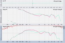
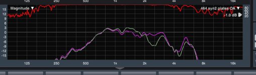
For example, the first yellow/orange trace below is with circular petals attached to the mouth of the 60x60, at the same flare as the horn. Look at the crazy dip at 2.4kHz. I was just spit-balling stuff.
I took the 60x40 apart, cutting back the apex, and fitting it with CD exit transition plates that worked well for the 60x60.
The plates didn't work nearly as well for the 60x40. So I tried the foam triangles/trapeziums. (Thx again freddi and billcowan, any further info appreciated...)
Anyway, the foam out at the mouth helps. But only on the vertical walls. They hurt placed anywhere on the horizontal walls.
Second trace is the dcx464 CD on the 60x40. yellow is without foam, and then with foam is purple. Learning, but damn these synergies are touchy beasts...
I get the general idea of where the HF and Lf are controlled. But dang the HF sure seem sensitives to well past the throat, all the way to mouth.
For example, the first yellow/orange trace below is with circular petals attached to the mouth of the 60x60, at the same flare as the horn. Look at the crazy dip at 2.4kHz. I was just spit-balling stuff.
I took the 60x40 apart, cutting back the apex, and fitting it with CD exit transition plates that worked well for the 60x60.
The plates didn't work nearly as well for the 60x40. So I tried the foam triangles/trapeziums. (Thx again freddi and billcowan, any further info appreciated...)
Anyway, the foam out at the mouth helps. But only on the vertical walls. They hurt placed anywhere on the horizontal walls.
Second trace is the dcx464 CD on the 60x40. yellow is without foam, and then with foam is purple. Learning, but damn these synergies are touchy beasts...
Attachments
- Status
- This old topic is closed. If you want to reopen this topic, contact a moderator using the "Report Post" button.
- Home
- Loudspeakers
- Multi-Way
- 100Hz two-way synergy project