My referents are to an offset driver (with a BP chamber) ported into a horn at S2. <snip>
seeing the directivity in HR sim will allow you to judge better what the effects of the holes are.
if only going down to 100 Hz with big drivers, it might not be worth the extra trouble of vented. I have an old sim using AE TD15H as "mids" on a 60x60 conical in bass reflex tuned to 35 hz. when I change it to sealed and high pass at 100 Hz, I can shrink the port from 120 cm2 to 45 cm2 at 120 db acoustic power. At that level, driver excursion is only 2.3 mm. but today I know that even that level is 10 or 20 db beyond what I need for use at home. Hole size could be even smaller, otoh, I would prefer to overlap the synergy with my woofer system at home at least down to 60 hz or perhaps with a single pole high pass filter for increased spatial diversity.
So you really have to have specific frequency and sound level goals to optimize the port size.
All you say makes sense to me...many thanks for the ongoing hornresp help.
I will post hornresp screens, as soon as I get stuck with what you've
suggested.
Totally on board re the bass-reflex ports...I'd love not to use them at all.
I do want a 100Hz crossover point though, and LOUD.
If I can get extension to there without BR ports, and the S2 horn entry ports can handle the velocity, I'll be very happy.
I typically use a LR12 to cross at 100Hz so almost no extension is needed below 100....might work")
One question about modeling directivity for a single section conical Nd, what kind of driver/parameters should be used? Or maybe, what do folks use for a compression driver. I've read TS parameters don't really apply, so I'm guessing there is a set of plug-in guesstimates folks use?
Overall, despite concerns with polars for the HF (500-6300Hz) section, I am really pleased with what I'm hearing, especially given the early state of development. The acoustic co-location rocks, huh?!!!
My kind of tea
I will post hornresp screens, as soon as I get stuck with what you've
suggested.
Totally on board re the bass-reflex ports...I'd love not to use them at all.
I do want a 100Hz crossover point though, and LOUD.
If I can get extension to there without BR ports, and the S2 horn entry ports can handle the velocity, I'll be very happy.
I typically use a LR12 to cross at 100Hz so almost no extension is needed below 100....might work
One question about modeling directivity for a single section conical Nd, what kind of driver/parameters should be used? Or maybe, what do folks use for a compression driver. I've read TS parameters don't really apply, so I'm guessing there is a set of plug-in guesstimates folks use?
Overall, despite concerns with polars for the HF (500-6300Hz) section, I am really pleased with what I'm hearing, especially given the early state of development. The acoustic co-location rocks, huh?!!!
My kind of tea
Watching with interest. Hope I'm wrong for your sake, but isn't there a path length issue with the coax compression driver? Otherwise all it would take to make a Synergy or Unity horn would be that magic CD at the throat and x-over. No silly midrange and ports needed
Do you mean the length between the coax CD's mounting flange and the diaphragm? I've been concerned with that too.
But at infocomm last month, I got to ask Tom Danley a few questions about my project. When i first said I was wanting to use the 4594 CD and cross at 500Hz, he immediately interjected that i could probably go straight to a 12".
I also asked whether the 1/4 notch distance should be figured from throat or from the diaphragm. He said from the throat because all the sound is going out from there..(which I've yet to grasp what he meant)
So anyway, like you, I'm very hopeful all will work without those 'silly midranges'
I feel that freq response going straight to 12"s will work for sure.
My only question now is, does having smaller midrange ports (which impact HF response less), allow the larger ports needed for the woofer to be moved out farther where they don't dick up the HF polars as much....
One question about modeling directivity for a single section conical Nd, what kind of driver/parameters should be used? Or maybe, what do folks use for a compression driver. I've read TS parameters don't really apply, so I'm guessing there is a set of plug-in guesstimates folks use?
I just change the "OD" to "ND" and then look at the Polar Map normalized. If I want to look at the other charts I use HR's equalizer to get a flat response. You don't care about the driver's response in this sim, you just want to see the directivity.
Well TS params do apply for CDs; they are just hard to get. I pulled these out of an Akabak script posted by JLH back in the early days of DIY synergy.

No surprise that Synergy sounds so good. Drivers are operated well within their linear limits and near ideal power response since no lobing issues or mismatched directivities between ways.
The only negative and one that can be managed is that a full range point source at ear level is going to suffer floor and/or ceiling bounce unless in a fairly large horn or in the middle of a woofer array that extends its vertical directivity.
So anyway, like you, I'm very hopeful all will work without those 'silly midranges'
I feel that freq response going straight to 12"s will work for sure.
My only question now is, does having smaller midrange ports (which impact HF response less), allow the larger ports needed for the woofer to be moved out farther where they don't dick up the HF polars as much....
The problem is that most CD's don't really like working below 1500Hz, and ideally 2500Hz in order to prevent them from sounding like they are distorted and harsh. That's why I like using full range drivers as tweeters - they go to 400Hz just fine. For home audio, you don't need the 115dB sensitivity of a CD and they sound rather harsh in my opinion.
that is why one doesn't use most CDs below 1500 Hz. But some CDs do very well there.
The BMS4550 used in early Danley Synergies is one of them. I cross it over at 1050 Hz in my Synergies and they have a beautiful top end, not the least bit harsh.
No less an authority than Earl Geddes used the oft cloned B&C DE250 in his highly regarded speakers at an XO of just under 1 khz. He said its all in how you do the crossover.
Yes, some CD's are well known to work going lower. I know I've been very happy with the BMS4594he on several different, relatively small, commercial horns, all crossed at 650Hz.
I'm hoping 500hz holds up too, on a bigger horn...we'll see.
We've seen that Cask05 has been happy with his 2" bms to maybe 400Hz or so..although he has a clearly superior horn to work with.
Got the DCX464 on order to give a try...supposed to be strong down low.
As far as crossovers for going lower, I believe it's a strong advantage to cross as steeply as possible, for reducing potential excursion problems and distortion. It also helps clearly helps vertical polars, at least in what I've built and measured.
But the catch is the need for linear phase crossovers.
I've settled in on 16th order LRs. (which btw, in a previous post I said I cross to subs @ 100Hz using LR12...meant 12th order LR.)
Jack, thx for the directivity direction
update:
Decided to go with best port configuration found to date, and build a box around the drivers that have been open so far. Trying to get ready for adding BR ports to 12"s.
It's been a very different process trying to dial in tuning than previous multi-way experiences.
Normally, I try to nail on-axis perfectly, and then watch degradation occur more and more as off-axis increases angle, degradation that is usually fairly uniform. Fix as necessary....
Not so with this synergy attempt. Off axis degrades more erratically.
I've found it best to use 10 degree off-axis as the center measurement, and then make sacrifice adjustments to help on-ax and way-off-axis.
Different divergence directions from 10 degrees off, heading towards on-axis, than further off.
Every design is diff, huh?
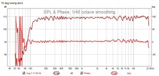
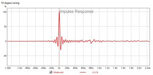
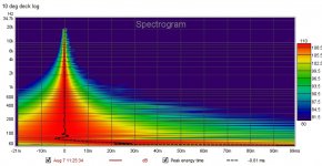
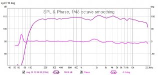
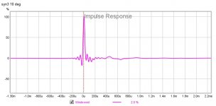
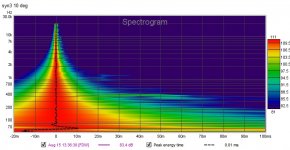
Anyway, below are the 10 degree tuning spot measurements, spl, impulse, and spectro.
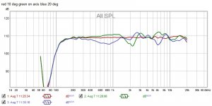
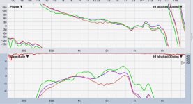
Followed by a a horizontal quickie plot : 10 deg, on-ax, 20 deg, ....to show the divergent tuning dilemma.
Feel like I'm getting there, slow but sure . The sound is remarkable, especially given the early state of development. Newly heard details and clarity.
Still alot to figure out with HF weirdness though...
Decided to go with best port configuration found to date, and build a box around the drivers that have been open so far. Trying to get ready for adding BR ports to 12"s.
It's been a very different process trying to dial in tuning than previous multi-way experiences.
Normally, I try to nail on-axis perfectly, and then watch degradation occur more and more as off-axis increases angle, degradation that is usually fairly uniform. Fix as necessary....
Not so with this synergy attempt. Off axis degrades more erratically.
I've found it best to use 10 degree off-axis as the center measurement, and then make sacrifice adjustments to help on-ax and way-off-axis.
Different divergence directions from 10 degrees off, heading towards on-axis, than further off.
Every design is diff, huh?
Anyway, below are the 10 degree tuning spot measurements, spl, impulse, and spectro.
Followed by a a horizontal quickie plot : 10 deg, on-ax, 20 deg, ....to show the divergent tuning dilemma.
Feel like I'm getting there, slow but sure . The sound is remarkable, especially given the early state of development. Newly heard details and clarity.
Still alot to figure out with HF weirdness though...
Attachments

I don't think that is so much a tuning dilemma as a horn issue. I think you made a good choice in that 10 degrees off axis should work well as the center of a listening window. There would be little to complain about in the primary seat even if you didn't keep your head still.
Try a shroud slipping over the front of the horn to implement a secondary flare, as Art Welter did on SynTripP, and things should get better, at least at 1 khz and below. Or try other kinds of mouth treatments. A naked single flare horn mouth, not even baffled, is worst case as I found out to my chagrin.
How did you do the round to rectangular conversion and subsequently smooth the throat? There might be some HF improvements available there.
Mark,Normally, I try to nail on-axis perfectly, and then watch degradation occur more and more as off-axis increases angle, degradation that is usually fairly uniform. Fix as necessary....
Not so with this synergy attempt. Off axis degrades more erratically.
I've found it best to use 10 degree off-axis as the center measurement, and then make sacrifice adjustments to help on-ax and way-off-axis.
Different divergence directions from 10 degrees off, heading towards on-axis, than further off.
Every design is diff, huh?
Conical horns do have some drawbacks, but your on axis vs off axis uniformity issues could be due to the conditions of measurement.
What distance from the horn mouth are you measuring at, and what is the axis of rotation?
Art
Looks very good! Looks like a great addition to the DIY family of Synergy design.
The shape of your box looks familiar
Looks familiar? It better, I totally copied your work
Thx for continued encouragement !
I don't think that is so much a tuning dilemma as a horn issue. I think you made a good choice in that 10 degrees off axis should work well as the center of a listening window. There would be little to complain about in the primary seat even if you didn't keep your head still.
Try a shroud slipping over the front of the horn to implement a secondary flare, as Art Welter did on SynTripP, and things should get better, at least at 1 khz and below. Or try other kinds of mouth treatments. A naked single flare horn mouth, not even baffled, is worst case as I found out to my chagrin.
How did you do the round to rectangular conversion and subsequently smooth the throat? There might be some HF improvements available there.
Totally agree, the tuning dilemma is the horn issue.
I spent a great deal of time working with the horn with no ports at all, smoothing the round to rectangular conversion you mention, and playing with different kinds of makeshift mouth dampeners, felt, blanket, etc,
All I ever got were minor reductions in freq ripple, but not an overall change in frequency pattern vs measurement angle.
Heck, I even stuck a pool stick into the throat up against the phase plug, and nothing changed much. Measurement distance matters most it seems.
I'm glad to see Art just replied...I've been looking forward to asking him about conical horns in general, and how to measure these.
Oh, last thought for now, I saw in an old post your idea for using tape-sense round overs at the mouth...that's prob the experimental direction i want to go...
Mark,
Conical horns do have some drawbacks, but your on axis vs off axis uniformity issues could be due to the conditions of measurement.
What distance from the horn mouth are you measuring at, and what is the axis of rotation?
Art
Hi Art, thanks for replying.
So far, all my measurements have been in the 1.5 to 3.5 meters from mouth camp.
1.5 indoors and 3.5 outdoors cause that's how far my mic boom extends past the deck.
At either of these distances, on-axis HF has a big dip at around 2kHz compared to 10-25 degrees off axis.
The only time on axis looks good is with mic in the horn.
Oh, and I should say this is with all ports blocked on the inside of the horn, with 22 gauge sheet steel.
Below is the HF coax section OA red, 15 blue , and 30 deg green: about 4ft from mouth.
What's the best way to measure here? I even built a spinorama for this puzzler
Attachments
Best way would be using a crane to suspend the cabinet far from any worldly influence...Hi Art, thanks for replying.
So far, all my measurements have been in the 1.5 to 3.5 meters from mouth camp.
What's the best way to measure here? I even built a spinorama for this puzzler
It does not sound like your measurements are in the far-field, and your description of your "spinorama" does not explain much.
Regarding your "spinorama"- the location of the horn's apex should be at the location of the turntable (or boom) rotation. That requirement makes turntables difficult, as the horn apex is near the back of the cabinet.
In regard to full range frequency measurements, Pat Brown wrote :
A working “rule-of-thumb” for determining the boundary between near-field and far-field is to make the minimum measurement distance the longest dimension of the loudspeaker multiplied by 3.
He then writes:
It is often thought that a remote measurement position is necessary for low frequencies since their wavelengths are long. Actually the opposite is true. It is more difficult to get into the far-field of a device at high frequencies, since the shorter wavelengths make the criteria in Item 4 more difficult to satisfy.
Item 4:
4. The distance from the source where the path length difference for wave arrivals from points on the device on the surface plane perpendicular to the point of observation are within one-quarter wavelength at the highest frequency of interest (Figure 2).
This is an important distinction between high frequency and low frequency measurement, criteria #4 can be satisfied at 95 Hz for a subwoofer of one square meter measured at one meter, but to satisfy the same criterion for a one meter mid/high horn to 16 kHz would require a very long distance.
All that said, your chosen horn wall angles may be problematic.
Although the 90x40 SynTripP polars for the most part are not as good as Peter Morris' DIY, they don't exhibit off-axis response louder than on-axis as your test unit appears to be doing.
This discussion may be interesting to re-read, now that you are "in the game" ;^):
Danley SH96HO biamping
Have fun!
Art
Last edited:
Best way would be using a crane to suspend the cabinet far from any worldly influence...
It does not sound like your measurements are in the far-field, and your description of your "spinorama" does not explain much.
Regarding your "spinorama"- the location of the horn's apex should be at the location of the turntable (or boom) rotation. That requirement makes turntables difficult, as the horn apex is near the back of the cabinet.
In regard to full range frequency measurements, Pat Brown wrote :
A working “rule-of-thumb” for determining the boundary between near-field and far-field is to make the minimum measurement distance the longest dimension of the loudspeaker multiplied by 3.
He then writes:
It is often thought that a remote measurement position is necessary for low frequencies since their wavelengths are long. Actually the opposite is true. It is more difficult to get into the far-field of a device at high frequencies, since the shorter wavelengths make the criteria in Item 4 more difficult to satisfy.
Item 4:
4. The distance from the source where the path length difference for wave arrivals from points on the device on the surface plane perpendicular to the point of observation are within one-quarter wavelength at the highest frequency of interest (Figure 2).
This is an important distinction between high frequency and low frequency measurement, criteria #4 can be satisfied at 95 Hz for a subwoofer of one square meter measured at one meter, but to satisfy the same criterion for a one meter mid/high horn to 16 kHz would require a very long distance.
All that said, your chosen horn wall angles may be problematic.
Although the 90x40 SynTripP polars for the most part are not as good as Peter Morris' DIY, they don't exhibit off-axis response louder than on-axis as your test unit appears to be doing.
This discussion may be interesting to re-read, now that you are "in the game" ;^):
Danley SH96HO biamping
Have fun!
Art
The near field / far field discussion seems spot on. That's really all i have left to try with this prototype. I'll go out in the driveway, both box and mic on the ground, 8m, like I usually do for subs or larger mains.
I think Pat Brown's point #4, and reflections off the horn walls are in play...hope truly far field solves them.
regarding the spinorama...I anticipated the need for apex at center and built a pretty big one...although I have to add a counterweight to spinning disc's *** to keep it balanced with the horn so far forward
Your memory and ability to recall threads and documents is awesome. Mine sucks. I recalled the SH96HO thread you linked, once I started reading it again. Hell, I even had a minor post in it..
At the time of the thread, I was really new to proaudio and DIY...I was just happy that the PM90 was being compared to the SH96's.
I chose 60x40 because I like 60 degrees keeping stuff off the walls, and I've read Tom Danley say to keep the aspect ratio, vertical vs horizontal, below 1.6x to avoid pattern flip.
So 40 seemed safe at 1.5x
If I leave the 60x40, it will probably be for a 60x60....
Thx Art!
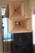
On to prototype #3 ! Pictured below without ports, on top of proto #2.
It's a small 60x60, using the same drivers as before. 4594he, and 2 mb12n351's.
I got proto2 sounding and measuring pretty good, but was troubled by the on-axis hole at around 2kHz, and also by horizontal pattern wavering as shown in post#29.
So I built the 60x60 with no ports, figuring any HF issues with no ports would be due to either:
bad CD exit matching,
mouth termination,
or the plain nature of square sided conical horns.
The hole at around 2kHz remains and so do the pattern issues.
I very carefully matching the CD's round exit to the square throat, so I think I can scratch that from the list of possible causes.
I can't rule out mouth termination, especially given the straight flares without any secondary flare, but i did attach some extra wings that didn't have much effect other than creating even more issues.
So I dunno...does anybody think a different CD would change things? All I have are the bms..
Anyway, I added the same mid port layout to proto3, and went on to tune the box by making measurement averages at 0,10, and 20 degrees horiz, for each section mid, hf, and vhf. Fairly reflection free off outdoor deck at 3m.
Then measured the tuning results at same degrees.
The best looking measurement occured at 10 deg, shown below.
0 and 20 degrees are a lit worse, but still close.
I thought the outdoor measurements looked pretty good, and set up to listen outdoors with high expectations....
Rolled off the high end a little, like on all designs and then listened...
Sounds like dog poo
Honky. Wrong. Even after knocking down the bump at 1.8-2kHz.
Oh well, back to it, sigh....
Attachments
1) Surprised to find the two horn geometries would have the same frequency "hole".1) The hole at around 2kHz remains and so do the pattern issues.
2) I very carefully matching the CD's round exit to the square throat, so I think I can scratch that from the list of possible causes.
3) I can't rule out mouth termination, especially given the straight flares without any secondary flare, but i did attach some extra wings that didn't have much effect other than creating even more issues.
4) So I dunno...does anybody think a different CD would change things? All I have are the bms..
5) The best looking measurement occured at 10 deg, shown below.
0 and 20 degrees are a lit worse, but still close.
Rolled off the high end a little, like on all designs and then listened...
Sounds like dog poo
Honky. Wrong. Even after knocking down the bump at 1.8-2kHz.
Oh well, back to it, sigh....
2) Agreed, throat anomalies would likely be higher frequency problems.
3) The secondary horn break will reduce "waist banding", which coupled with the 2kHz problems you are complaining about could make for a better overall impression.
4) Good question, it would be interesting to see what your BMS co-ax dispersion looks like with no horn.
5) Hard to tell what you did compared to what was shown at 10 degrees, but that shows a couple upper 3 dB "honks" relative to the downward trend starting at 1kHz.
Oh well- you might be finding out first hand why Keele went from a career in horns to the CBT array ;^).
Cheers,
Art
Oh so that is a result of equalizing to averaged measurements, 0, 10, 20 degrees? My own results with a similar horn tell me that 40 degrees is too wide a span to expect good performance. My own goals were less ambitious. I got good performance over 3 adjacent seats on a couch and declared victory. That was likely just a 10 or 12 degree span.
The trouble is that the conical horns we can build don't control directivity very well and the ones that do, like the SEOS family, are either too small or too expensive.
The trouble is that the conical horns we can build don't control directivity very well and the ones that do, like the SEOS family, are either too small or too expensive.
- Status
- This old topic is closed. If you want to reopen this topic, contact a moderator using the "Report Post" button.
- Home
- Loudspeakers
- Multi-Way
- 100Hz two-way synergy project