This is my first post on DIY Audio, although I have been following many of the forum posts on speaker projects for over three years. It seems that whenever I do a Google search regarding speaker design, DIY Audio Forum posts are at the top of the list generated (of real information).
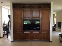
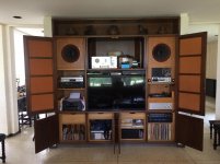
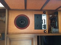
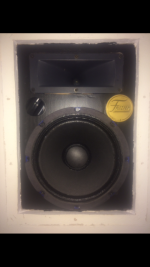
Five years ago my wife and I purchased a very unique modern design home that was built in 1967. The house was equipped with every possible high end feature available, including close circuit TV, electric curtains, solenoid controlled lighting from a central panels (one panel built into the master bedroom night stand controls every light in the house), stereo speakers in the ceiling of every room but one (Frazier of Dallas 1.5 cuft cabinet speakers with 8" Altec woofers and Foster horn tweeters), Sony RTR player, Dual 1009SK turntable, and a Fisher tube receiver (Fisher unit long gone). The one room without Frazier ceiling speakers is the "Media Room", which has 15" Wolverine LT15 triaxial speakers built into a walnut wall media cabinet . See attached photos.
I spent last year (with the guidance and help of a great guy Glen) sorting out the Frazier speakers, rebuilding the original drivers, building new crossovers, and tuning the cabinets. if you are interested in more information, I posted the restoration process at Vintage 1967 Built In High End Home Hi Fi | Audiokarma Home Audio Stereo Discussion Forums
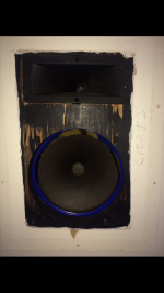
This year I am attacking the Media Room system. Originally I planned to reuse the Wolverines and tune the cabinets properly. The builders of the media center cabinets were fine wood working craftsmen, but lousy speaker cabinet designers. But I am getting older, and If I am going to invest my scarce time in a project, I want it to be the best I can afford. So the Wolverines are destined for eBay.
Over the past year I have spent many hours sketching different speaker configurations for the media center. Most of them utilized the Altec 604 coaxial as the basis. I started off trying to keep some of the electronics in the two side areas behind the hinge screens. But I came to the conclusion that it was best to make use of all the volume on the sides, and relocate all electronics to the area above the TV. This area (originally for the TV) is nice and deep, ventilated, and can be totally hidden by two doors that slide out from either side to disappear when open. This also gives me the freedom to change electronics more easily should I want to play with different amps, preamps or sources.
I thought I would try to fit an MTL configurationinto the space available. While I could just about make it fit, the compromises I needed to make did not guarantee success. While volume was adequate, port location and cross-sectional area were not optimal. Going back to a conventional bass reflex design was the best option. But I was hoping to get deeper base in the conventional 604 would get in a bass reflex cabinet. Also the 604 tweeter height was a little bit taller than my seating height on the couch. Without electronics in the area I could mounted lower, but the screens on the doors have woodframe bars that would block the tweeter with the door closed. So a complete re-think was required. FYI Wife is very understanding, but one house rule is that with the door closed the cabinets must look the same. I also do not want to butcher these beautiful walnut cabinets.
I had been reading a lot about the Altec Model 19, and had heard only good things. So using the dimensioned drawings I found of the Model 19 cabinet my plan changed course. Using the modern GPA 416-8B in a 8.8 cuft bass reflex cabinet gets me a respectable 25 Hz bottom end (according to GPA). While installing the the Altec 811-B horn below the 416 can get me the tweeter height closer to optimal. Reading the Model 19 manual I even discovered instructions on how to position the cabinets upside down for studio use. As a final bonus, the drivers clear almost all the screen obstructions.
I was looking for some sign from the audio gods to tell me if this was the best direction to go with the cabinet design. The sign came from an ad on eBay forAltec 811 horns for sale in perfect originalcondition, and just 15 minutes drive from my house. Within one hour of seeing the ad I purchased the horns and brought them home.They were just as described perfect condition and they only cost me $90. In seeing these huge aluminum monstrosities my wife commented "Well if you don't use them for the speakers, I can make them into some very interesting flower vases�.
Over the past year I have been putting aside funds for this project. Last week I communicated with Bill at GPA, and told him I would be putting in an order for all the parts I needed within the next few weeks. Oklahoma City is just a 3 hour drive North of me. So I can pick up all the components and save both shipping and worry.
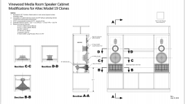
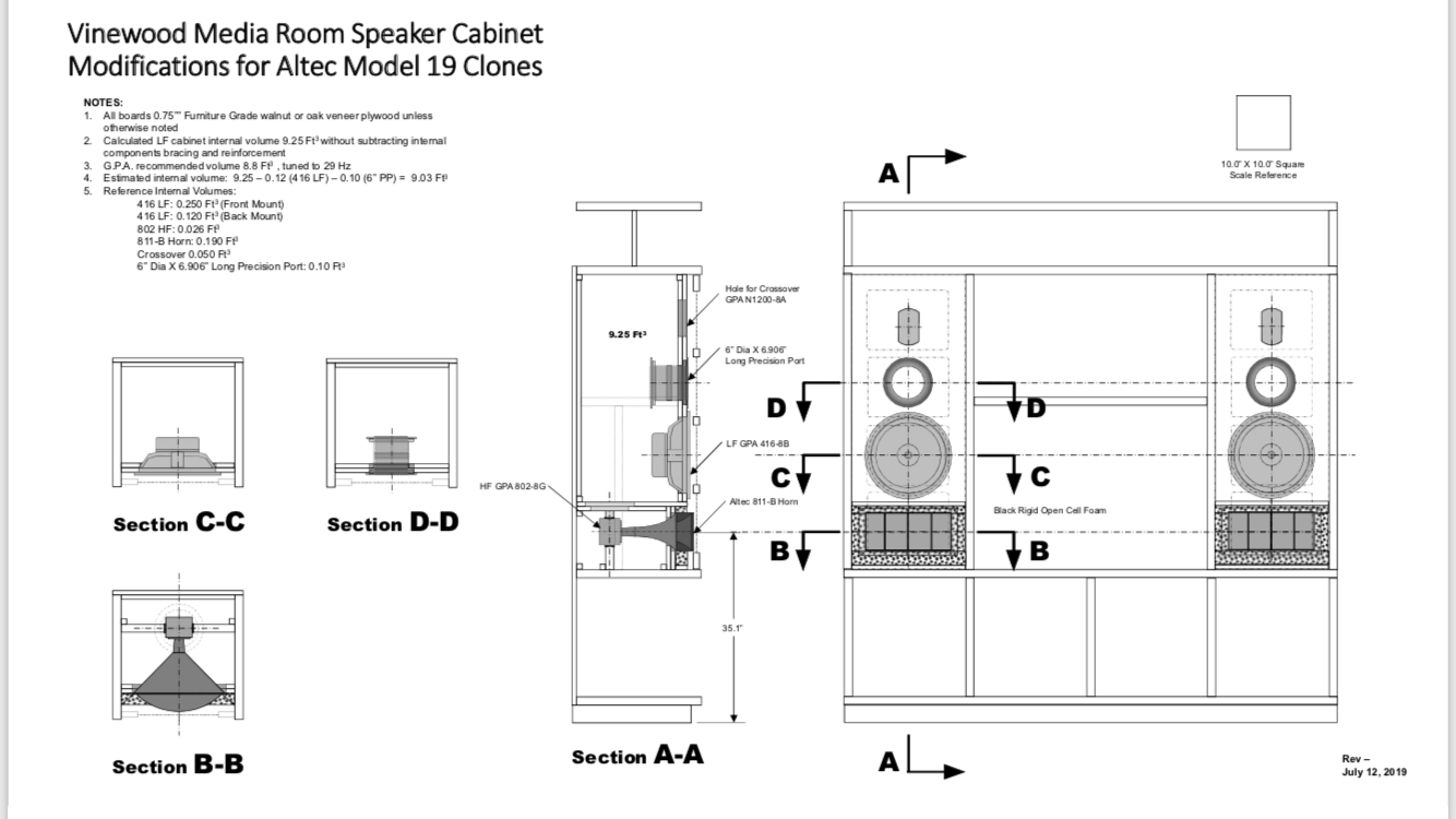
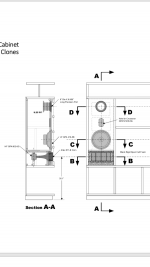
Now I need some input and comments from the DIY Audio community. Please take a look at the attached plans (low resolution in photo, high res in PDF) and let me know what you think. I am especially interested in any comments regarding the port location and size, placement and type dampening material to use, and any thoughts concerning cabinet rigidity. Note that I have isolated the HF horn completely from the LF volume. I have also moved the LF and HF drivers closer together. Depth of driver mounting is identical to the Model 19.
The top,bottom, and sides of the cabinets are 1.50" furniture grade plywood (no voids). The front and back of the cabinets will be 0.75"� furniture grade plywood with0.75" MDF bonded to it. I am thinking that with this thickness there is no need for any internal bracing. But I need some reassurance.
All comments and suggestions welcome.
Thanks in advance.
Five years ago my wife and I purchased a very unique modern design home that was built in 1967. The house was equipped with every possible high end feature available, including close circuit TV, electric curtains, solenoid controlled lighting from a central panels (one panel built into the master bedroom night stand controls every light in the house), stereo speakers in the ceiling of every room but one (Frazier of Dallas 1.5 cuft cabinet speakers with 8" Altec woofers and Foster horn tweeters), Sony RTR player, Dual 1009SK turntable, and a Fisher tube receiver (Fisher unit long gone). The one room without Frazier ceiling speakers is the "Media Room", which has 15" Wolverine LT15 triaxial speakers built into a walnut wall media cabinet . See attached photos.
I spent last year (with the guidance and help of a great guy Glen) sorting out the Frazier speakers, rebuilding the original drivers, building new crossovers, and tuning the cabinets. if you are interested in more information, I posted the restoration process at Vintage 1967 Built In High End Home Hi Fi | Audiokarma Home Audio Stereo Discussion Forums
This year I am attacking the Media Room system. Originally I planned to reuse the Wolverines and tune the cabinets properly. The builders of the media center cabinets were fine wood working craftsmen, but lousy speaker cabinet designers. But I am getting older, and If I am going to invest my scarce time in a project, I want it to be the best I can afford. So the Wolverines are destined for eBay.
Over the past year I have spent many hours sketching different speaker configurations for the media center. Most of them utilized the Altec 604 coaxial as the basis. I started off trying to keep some of the electronics in the two side areas behind the hinge screens. But I came to the conclusion that it was best to make use of all the volume on the sides, and relocate all electronics to the area above the TV. This area (originally for the TV) is nice and deep, ventilated, and can be totally hidden by two doors that slide out from either side to disappear when open. This also gives me the freedom to change electronics more easily should I want to play with different amps, preamps or sources.
I thought I would try to fit an MTL configurationinto the space available. While I could just about make it fit, the compromises I needed to make did not guarantee success. While volume was adequate, port location and cross-sectional area were not optimal. Going back to a conventional bass reflex design was the best option. But I was hoping to get deeper base in the conventional 604 would get in a bass reflex cabinet. Also the 604 tweeter height was a little bit taller than my seating height on the couch. Without electronics in the area I could mounted lower, but the screens on the doors have woodframe bars that would block the tweeter with the door closed. So a complete re-think was required. FYI Wife is very understanding, but one house rule is that with the door closed the cabinets must look the same. I also do not want to butcher these beautiful walnut cabinets.
I had been reading a lot about the Altec Model 19, and had heard only good things. So using the dimensioned drawings I found of the Model 19 cabinet my plan changed course. Using the modern GPA 416-8B in a 8.8 cuft bass reflex cabinet gets me a respectable 25 Hz bottom end (according to GPA). While installing the the Altec 811-B horn below the 416 can get me the tweeter height closer to optimal. Reading the Model 19 manual I even discovered instructions on how to position the cabinets upside down for studio use. As a final bonus, the drivers clear almost all the screen obstructions.
I was looking for some sign from the audio gods to tell me if this was the best direction to go with the cabinet design. The sign came from an ad on eBay forAltec 811 horns for sale in perfect originalcondition, and just 15 minutes drive from my house. Within one hour of seeing the ad I purchased the horns and brought them home.They were just as described perfect condition and they only cost me $90. In seeing these huge aluminum monstrosities my wife commented "Well if you don't use them for the speakers, I can make them into some very interesting flower vases�.
Over the past year I have been putting aside funds for this project. Last week I communicated with Bill at GPA, and told him I would be putting in an order for all the parts I needed within the next few weeks. Oklahoma City is just a 3 hour drive North of me. So I can pick up all the components and save both shipping and worry.
Now I need some input and comments from the DIY Audio community. Please take a look at the attached plans (low resolution in photo, high res in PDF) and let me know what you think. I am especially interested in any comments regarding the port location and size, placement and type dampening material to use, and any thoughts concerning cabinet rigidity. Note that I have isolated the HF horn completely from the LF volume. I have also moved the LF and HF drivers closer together. Depth of driver mounting is identical to the Model 19.
The top,bottom, and sides of the cabinets are 1.50" furniture grade plywood (no voids). The front and back of the cabinets will be 0.75"� furniture grade plywood with0.75" MDF bonded to it. I am thinking that with this thickness there is no need for any internal bracing. But I need some reassurance.
All comments and suggestions welcome.
Thanks in advance.
Attachments
Last edited:
Nice! project Aeroaudio.
I see two different sets of furniture here ?
Personally, I'd hide the big ducted port ( or just make it a simple slot port located at the top of the baffle board ). I'd also hide the crossover face/knobs ( within a drawer maybe ?? ).
Aesthetically, I'd prefer to see nothing but an expanse of nice wood grain above the woofer ( but that's just my opinion as if it were my stuff ).
I like the horn height and woofer layout / that should work well enough for you ( & the shortish throw distance to the couch and glass ).
I'd also advise to the making of a plain mockup ( removable ) plywood baffle-board where you can experiment with different box tunings ( and maybe port locations ).
It's not a slam-dunk that you're going to get the bass response that you expect and want due to this media center effectively being located ( acoustically ) in a much larger room than its immediate location.
Locating the woofer almost 1/2 way between floor and ceiling will trigger some rarely encountered room modes ( exactly which ones, I can't really tell you ).
You'll want to get a test mic and learn to use something like REW ( to help identify and then tame your somewhat hostile room acoustics > from all the glass & polished marble/terrazzo ).
")
An externally hosted image should be here but it was not working when we last tested it.
I see two different sets of furniture here ?
An externally hosted image should be here but it was not working when we last tested it.
Personally, I'd hide the big ducted port ( or just make it a simple slot port located at the top of the baffle board ). I'd also hide the crossover face/knobs ( within a drawer maybe ?? ).
Aesthetically, I'd prefer to see nothing but an expanse of nice wood grain above the woofer ( but that's just my opinion as if it were my stuff ).
I like the horn height and woofer layout / that should work well enough for you ( & the shortish throw distance to the couch and glass ).
I'd also advise to the making of a plain mockup ( removable ) plywood baffle-board where you can experiment with different box tunings ( and maybe port locations ).
It's not a slam-dunk that you're going to get the bass response that you expect and want due to this media center effectively being located ( acoustically ) in a much larger room than its immediate location.
Locating the woofer almost 1/2 way between floor and ceiling will trigger some rarely encountered room modes ( exactly which ones, I can't really tell you ).
You'll want to get a test mic and learn to use something like REW ( to help identify and then tame your somewhat hostile room acoustics > from all the glass & polished marble/terrazzo ).
Last edited:
Thanks for the input EarlK.
The circular port was not my first choice in configuration. Original layouts used a slotted port. But unlike typical speaker cabinet construction, the installation allows no access to the back or sides of the speakers. Everything needs to be accessible from the front. To attach the baffle board I will be using lag screws that will be accessible by reaching through the speaker hole and the port hole. I can get my arm through a 6” diameter port hole, but I cannot reach through a 2.5” slot. So the round port lets me reach the upper bolts.
For initial trials I will use the plastic Precision Port. But it will be replaced later with a turned wood port.
The listening position is 12’ from the speakers. The floor in front of the speakers had a heavy shag rug, and the window facing the speakers are covered with heavy drapes. This should help dampen the hard reflective surfaces. Also the media room is not too large, about 15’ X 15’.
A series of trial baffle boards is a good idea. Will play with different configurations. Will also look at different locations for the L pads.
FYI. Some of my posted photos are from the prior owners furniture.
I hadn’t intended to discuss the room acoustics in this post. Other than wall and floor surface treatments there are no changes acceptable. As Earl points out, the media center is not connected to the side walls, but is open floor to ceiling on both sides by four feet. Behind the media center is a large open floor plan with the nearest wall over 28 feet away. It would be interesting to know what affects this will have on room acoustics. But there is really nothing I can do to change this room configuration.
The room ceiling is 8 ft and the woofer will be 49” above the floor. So half way up as Earl states. But I have seen many 604 duplex cabinet designs with the driver located close to this height. So is this a concern?
The room ceiling is 8 ft and the woofer will be 49” above the floor. So half way up as Earl states. But I have seen many 604 duplex cabinet designs with the driver located close to this height. So is this a concern?
Greets!
Got plenty to say and not much time ATM, so may be awhile and/or in 'snippits' such as your 'game' changing floor/ceiling eigenmodes causing a huge/deep fundamental null that theoretically will 'suck the life' out of any speaker output centered at ~565 ft/8 = ~70-71 Hz, which of course is where the vocals, most music's 'foundation' is and no practical amount of extra power will overcome it, though not for lack of lots of folks over time trying and have the burned up driver VCs and/or amps to prove it.
Wouldn't hurt to join the AUB also if not already since there's lots of M19 centric folks there: Altec User's Board
GM
I hadn’t intended to discuss the room acoustics in this post.
But I have seen many 604 duplex cabinet designs with the driver located close to this height. So is this a concern?
As I just noted, the room dominates, so the driving force behind any speaker design suggestions [at least on my part], so can't have too much detailed info on it.
If with 8 ft. ceilings, you may rest assured that there's a notch in the 604's response in the 70-80 Hz BW, one of several worst places for a notch to be WRT a potentially above average performance IME, but we all hear the same, yet not so much, so as always YMMV.
GM
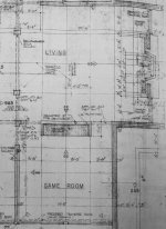
GM, I was hoping you would respond to my post. Regarding your request for more detailed info, attached is a photo of the house's floor plan blueprint showing the media room dimensions, and the living room behind the media center wall.
The woofer I plan to be using is the Model 19's 416-8B. I was just referring to the driver height of some cabinet designs using the 604. The only other knob I have available to turn is the baffle board inclination. I can incline it down a few degrees if it can help in any way.
Attachments
I tried helping on several sites including GPA before the buyout/reconstruction and while I helped some, the basic structure of FB is no place for any serious effort nor long term storage for reference, so basically avoid it like the plague.
Re the room, pretty much what I feared, got a ~same divided room situation locally, though his is a large separates horn system, so some flexibility.
Regardless, the 'heart'/'magic' of the M19 is its XO combined with driver spacing and offset, so need to adhere to the factory spacing dims as close as practical.
Ideally, the width/height of the horn recess should be the same with replica foam inserts, though IIRC these are no longer available, so either DIY something close or line with 1" acoustic fiberglass insulation same as the early M19, Valencia 846B and 878B Santiago.
The closed off horn box should be ~stuffed with blocks of rafter fiberglass insulation or better still, open it up like the M19 for some extra net volume [Vb] and just damped like it.
The Woofer box appears long enough to justify centering the vent at L [i.d.]*0.848, so up near the top or a shelf vent at the very top or either located out of sight on the top [each will have minor tuning differences].
Then there's the room modes to consider and while we can assume where the modes theoretically are, we don't know how lossy the floor or ceiling is, so short of mapping it they may be offset one way or the other.
Know any roofing, foundation details?
GM
Thank you for the input GM. Attached is a Rev A drawing showing the port center relocated to 0.848 X the box inside height dimension. Any thoughts on port configuration? Round versus rectangular, single versus dual, etc?
The spacing between the horn and the woofer is currently slightly smaller than on the 19. But if it is critical I can match the 19 spacing. I changed it to better match the grill openings, but most of the time the doors with the grills will be open.
I have enough volume to meet the GPA recommended 8.8 ft.³ for the 416 woofer without adding the volume around the horn. Plus people have commented that it is beneficial to keep the volumes between the horn and the woofer separate. Personally I want to keep the volume for the horn separate to allow me to re-position the angle without affecting the sealing of the cabinet.
Regarding construction of the room. The floor is pier and beam construction. Floor joists are 2” x 12” on 12” centers. The terrazzo floor is 8” thick concrete and quartz stones. The flat roof ceiling is also 2” x 12”s, but on 18” centers. It is also a flat roof, so the space between the ceiling and the roof is stuffed with fiberglass installation. The surface of the ceiling is not conventional American drywall but is what is called here plasterboard. Which is both thicker and smoother. FYI, the walls are not plaster but are double row brick construction. The left wall however is covered with a tapestry like material floor to ceiling.
Attachments
You're welcome!
Round is most efficient, ergo shortest due to lowest friction losses. That said, the full width shelf vent is physically shortest due to having three walls to 'finish' it [biggest end correction]. Square where its area = round area and rectangular up to a ~1: 1.273 ratio where the short side is the pipe's circumference/4 and the the long side is the diameter of the pipe are acoustically close enough to it.
I normally recommend round since it's best and so many folks can easily cut it out quickly plus easiest to test different tunings, though use rectangular when just a predetermined material thickness reflex slot and only bother with shelf vents when it needs to be unacceptably long.
Altec seems to have spent considerable time determining the cab/drivers/XO 'system', but not having researched it nor reading anything other that marketing hype, all I can say is YMMV, though tilting larger horns perched on top out in the open can audibly impact summed polar response. Not an exact example, but from this you can imagine how tilting the horn will shift pattern: Linkwitz-Riley Crossovers: A Primer
Based on factory drawings, component volumes, the M19 is ~15,789.6875"^3 gross, less ~890.688"^3 = ~14,899"^3 = ~ 8.62106 ft^3 net, so GPA's 8.8 ft^3 gross is a little small, but not audibly so and maybe uses more accurate component volumes.
OK, so the eigenmodes will in theory shift up a bit from the floor and across from the brick wall, then if you ever measure them in room it might help explain peaks/dips not lining up too well.
Got a busy next few days, so will be awhile before seeing how the speakers line up with the major modes unless you or others tackle it, though vent location appears to be the only variable.
GM
Check Out Rev B to Cabinet Design
Well I am finally back home and have some time to revise the Model 19 cabinet design to incorporate GM's and other DIY member comments. Thank you.
The Rev B changes are as follows;
1) 811B horn has been raised 3.5" to 38.6", Closer to ear height.
2) 416-8B woofer CL distance to horn CL change to match Model 19.
3) Horn and woofer now occupy one cabinet volume, which;
a) Simplifies cabinet construction.
b) Reduces cabinet depth to be less square.
c) Provides more than enough volume for bracing and tuning (1.0 cut).
4) Crossover L-Pad panel rotated 90 deg and moved to below the horn. This will require I fabricate a new panel. But the GPA panel is not as classy as the original Altec panel anyway. I can get some brass panels made at a local trophy shop with the Altec logo silk screened on.
5) Grill support on door now centered across middle of woofer. But doors will be open for serious listening anyway.
No sawdust is on the floor yet. So more comments are welcome. Copy of Rev B drawing attached.
Attachments
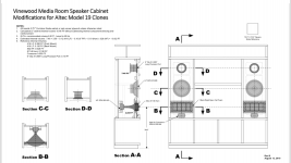
Final Custom Built In Altec Model 19 Cabinets Rev C
Was hoping to get some more thoughts from GM or others on the Rev B version of the cabinet plans I posted last week. But in the absence of any additional comments, they must be perfect. Right?
Well not perfect enough for me at least. So therefore attached is Rev C, what should be the final version. Barring any unexpected discoveries when I cut the front off the old cabinets and see what is back there.
Changes from last time are mostly fine tuning and details.
a) Front and back now 1.50" thick, matching the thickness of the existing cabinet sides and bottom. The 0.75" Baltic Birch isn't that expensive for the little I need.
b) Back of cabinet positioned to reduce excess estimated cabinet volume to 0.3 cubic ft over the optimum 8.80 cubic ft. Enough to provide for tuning and unexpected added bracing. Although with all sides 1.50" thick, I don't expect any added bracing will be required.
c) Details on corner reinforcements and L-pad installation added.
For grins I did a estimate of how much the completed cabinets would weigh if they were designed as stand alone speakers. About 220 LBS each. Good thing I will never need to move them.
Heading out of town again for a week. Will begin ordering all necessary components, hardware and wood when I get back. Any last minute comments or ideas welcome.
Attachments
What's to check? No dims on rev B. Forgot about the eigenmodes, but the layout is too 'fixed', so it is what it is.
Rev C: I have a 17.25" ctc spacing and an i.d height of 46.1/0.848 = 54.36" based on recommended vent offset.
0.3 ft^3 isn't enough to audibly affect tuning.
GM
Rev C: I have a 17.25" ctc spacing and an i.d height of 46.1/0.848 = 54.36" based on recommended vent offset.
0.3 ft^3 isn't enough to audibly affect tuning.
GM
Thanks GM. You are correct in that the design of my box is literally boxed in for many parameters.
Thanks for your assistance. Time to start making sawdust.
Other than application of insulation to one opposing side, any specific recommendations on type and thickness to use?
Thanks for your assistance. Time to start making sawdust.
Other than application of insulation to one opposing side, any specific recommendations on type and thickness to use?
You're welcome!
Damping a cab can be technically correct or to 'taste'.
Technically correct is when there's just enough to stop the box from sounding 'hollow' and the vent from 'ringing', both under damped conditions that is tested with an impulse response. Before the advent of readily available computer software the [advanced] DIYer used the 'click' test: Click Test | GM210 | Flickr
Like any decent manufacturer, Altec 'optimized' each model as required in that it started technical, then was adjusted in various ways, locales, etc., till the bean counters hollered 'enough already'! In Altec's case it increasingly became a 'toss a wad' of fiberglass insulation in the box and be done with it like seen in later M19s.
Many cabs just had one side, back and the top or bottom covered, whichever was opposite the vent and often not even on the full panel because it was found that only ~70% of the area was required. 'A penny saved......'
Most cabs used 1" thick acoustic fiberglass insulation [AKA O.C. 703 duct board nowadays] loosely held in placed and some 2" thick, so if one layer doesn't do it for you........while others are heavily stuffed due to various reasons.
Most folks on the various forums prefer healthier materials with denim insulation, polyfil, being the most common AFAIK with the latter normally requiring netting to keep it out of the components. Open cell foam, felt carpet pad, all sorts of stuff is used, but for Altec, recommend the 703 FG since that's what they 'voiced' with after it was invented, before was a treated paper, some made into a semi-flat bag filled with ground up treated paper, but its name escapes now.
So start with just some on the back, bottom, one side wall opposite the woofer [not the whole panel unless later feel the need for it] and do the click or impulse test plus however else you 'voice' speakers [test CDs/whatever] as a surprising number of folks like the cab adding a bit resonance, especially if only listening to CDs and go from there if not happy. Be sure and shelve/tone down the horn to be as tonally balanced [flat] through the XO BW [out to ~2500 Hz] and ignore dialing in the HF roll off till done with damping.
GM
- Home
- Loudspeakers
- Multi-Way
- Alec Model 19 Custom Built-In Cabinet Plans