It sounds as though we both see this as a source of fatigue. I can only imagine why we experience it differently.signal recovery process.
Hello All,
Not for lack of trying, I have never found a definition of HOM. I have never seen a mathematical model of an HOM. I have never seen HOM’s on an oscilloscope. I have never see HOM’s on an audio analyzer.
If you ever see a HOM take a picture and post it hear.
The bulk of the identifiable and objectionable horn sound is due to diffraction, reflections and diaphragm breakup. These are all well-defined and measurable. They are not HOM’s.
The best way to get away from the sharp edge sound of horns is to remove the physical edges; flat reflecting surfaces and only cross over to a horn above the delicate midrange frequencies.
The call of the horn and Directivity Index is a topic for another day.
Thanks DT
Last edited:
It is energy which originates from the primary mode, but which follows a different path, as it is diverted. Ie another mode of the original source.I have never found a definition of HOM.
but these are necessary to do the job of the horn.is to remove the physical edges; flat reflecting surfaces
If HOM is Higher Order Modes then this is a straightforward technical term that means all the modes (resonances) that are not the main axial mode/s. For horns it becomes an issue if some of the energy in the wavefront that one wants to travel axially down the waveguide and radiate away is diverted into other directions. This happens at sharp edges and anywhere the wavefront is not exactly 90 degrees to the wall. This unwanted energy will drive the waveguide resonances producing resonant spikes in the measured transfer function. To see them in measurements the frequency needs to be sufficiently resolved not to average or smooth them away (rare) and for you to be able to pick them out from all the other resonances typically produced by high efficiency speakers.Not for lack of trying, I have never found a definition of HOM. I have never seen a mathematical model of an HOM. I have never seen HOM’s on an oscilloscope. I have never see HOM’s on an audio analyzer.
it is plain old reflection
Yes horns do have edges and parallelish reflective surfaces. As we move to a well lathered and used bar of soap shape those edges and reflective surfaces are smoothed. Just for example Tractrix horns are much smoother looking and sounding than an old school Bi-Radial horn.
What I get out of HOM’s is this: direct sounds are lower order and radiate more or less directly out of the horn. Other frequencies not only radiate directly they bounce around off the walls of the horn as they radiate by an indirect route. The indirect radiation can be said to be delayed, or phase delayed and have amplitude distortion. This is not the hypothetical construct called HOM, it is plain old reflection. The phase delayed and amplitude distorted frequencies are dependent on the geometry of the horn. Softer shape horns sound less like horns.
For grins look at the impedance plots of a several horns, horns have multiple impedance peaks. If you turn off all of the software smoothing functions you will see many smaller impedance peaks that I call saw teeth. Impedance peaks are caused by reflections. Horn impedance plots smooth out typically above 2000Hz to 2500Hz. Even the old school Bi-Radial horns sound less horn like above 2 KHz.
The theory of the foam in the horn throat is that the indirect reflections take longer to transverse the length of the horn and as a result are attenuated more than the direct output.
Thanks DT
Hoping you don't fall into the trap of thinking that if baffles cause diffraction, we need speakers without baffles.As we move to a well lathered and used bar of soap shape those edges and reflective surfaces are smoothed. Just for example Tractrix horns are much smoother looking
The bar of soap analogy represents a typical arbitrary disbursement of diffraction at a practically convenient time. The tractrix horn is a constant stream of diffraction.
Name you horn, name any example waveguide. There is diffraction and reflection everywhere.
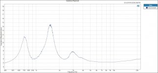
See the attached JBL M2/D2 impedance plot. Note there are 3 count them, impedance peaks plus more sawteeth than I can count.
That D2 driver is really cool, there is no diaphragm breakup on the impedance plot.
It is a wounder what Digital Signal Processing can fix, thanks to Crown.
Thanks DT
See the attached JBL M2/D2 impedance plot. Note there are 3 count them, impedance peaks plus more sawteeth than I can count.
That D2 driver is really cool, there is no diaphragm breakup on the impedance plot.
It is a wounder what Digital Signal Processing can fix, thanks to Crown.
Thanks DT
Attachments
Last edited:
Hello All,
Not for lack of trying, I have never found a definition of HOM. I have never seen a mathematical model of an HOM. I have never seen HOM’s on an oscilloscope. I have never see HOM’s on an audio analyzer.
If you ever see a HOM take a picture and post it hear.
Thanks DT
Please review pages 6-9 here. This paper is several years old and has been posted here many times.
Please review pages 6-9 here. This paper is several years old and has been posted here many times.
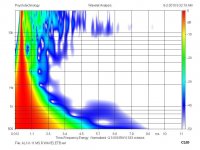
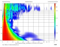
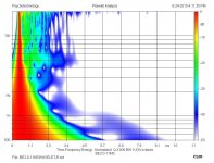
I have always been a bit skeptical about the claims made in that paper. It's not peer reviewed and does not address what's going on with the compression drivers themselves. It just takes a driver horn measurement and attempts to put all the issues in the wavelet response as attributed to only the horns. Attached are 3 wavelets measured on a planewave tube using the same compression driver body and phase plug. The differences are all from the diaphragm materials only. Comparing to the measurements with the horns how could you possibly say with any certainty where the HOM issues have their roots. Or even if they are really HOM's at all looking at the materials measurements. That's Aluminum Titanium and Be and the paper they are from.
Truextent White-paper for Large Format Diaphragms
Rob
")
Attachments
Last edited:
My first impression is that the saw teeth look like a measurement artefact - noise, truncation, FFT bins, whatever....plus more sawteeth than I can count...
Are they consistent and repeatable?
Absent for a direct radiator with the same test set up?
Best wishes
David
My first impression is that the saw teeth look like a measurement artefact - noise, truncation, FFT bins, whatever.
Are they consistent and repeatable?
Absent for a direct radiator with the same test set up?
Best wishes
David
That was my impression too.... the saw teeth look like a measurement resolution that's just too fine to be real ???
Hello,
Yes that is exactly what I thought as well. “Oh look at that, I wonder what is going on there”?
I ran it again, same thing. I set the instrument to append and ran the sweep several times, each time the sawteeth were exactly on top of each other. Exactly consistent.
Then I ran an impedance sweep on a couple of different cone speakers, no saw teeth.
Next I did a sweep of another JBL CD Horn combo, more sawteeth.
I used Audio Precision procedures and instruments. APx555 and APx1701.
https://www.audioxpress.com/files/attachment/2620
Thanks DT
Interesting re: sawteeth. I assume the mic was spaced reasonably well from the horn throat- high frequency reflections could cause that ripple. I've never had sawteeth like that from any horn I've measured, but have definitely seen multiple higher-Q impedance spikes. Might just be a resolution thing, as that is quite high frequency noise.
Hello All,
There is no microphone used in the impedance plot. The impedance plot is one of the outputs from the AP500 software Theile Small Sequence of tests.
How the APx500 software and APx1701 works is like this. The frequency sweep is a logarithmically spaced series of test points. There is a precision sensing resistor in series with the Driver Under Test, DUT. Recall that Voltage equals Current times Resistance, E=IR. Measuring the voltage across the known resistance of the sensing resistor we can calculate the series current. Now the voltage is also measured across the DUT. Know knowing voltage across the DUT and the current through the DUT impedance is calculated for that specific frequency sampling point, each point of the logarithmically spaced series of test points is placed on the graphic plot. In the absence of any Spline or other curve fitting the plot with the sawteeth is a plot of the frequency sweep data points with short straight line segments connecting the points.
Not having access to the code this is my best SWAG at it. It is all pretty much complex algebra to me.
Take a look at this AUTOCAD help page.
AutoCAD 2010 User Documentation
No I have not yet swept a small dome tweeter.
Thanks DT
Last edited:
There is no microphone used in the impedance plot.
Too funny. I know that but had a brainfart- I was thinking about diffraction sources in the horn (JBL's distributed HF diffraction is one of the design features of the M2 horn) and didn't even consider that we're talking impedance, not FR.
- Status
- This old topic is closed. If you want to reopen this topic, contact a moderator using the "Report Post" button.
- Home
- Loudspeakers
- Multi-Way
- Why do HOMs Suck?