If you think that a high impedance network (like a passive crossover) between the amp and the drivers is not spoil the driver's Qes, then i don't know what to say.
Question: What passive crossover has that kind of in-passband impedance???
Answer: None! So dont' crap your pants over some ridiculous BS sentiment that a passive crossover is a "high impedance network" ! You are totally wrong on this point.
What I can say is that "high impedance" compared to, say, an 8 Ohm driver is on the order of 100 Ohms or higher.
At best a junky low cost crossover will put a series resistance of at most 1 Ohm in series with the driver. That's still at least several times less than the DC resistance of a home audio driver. Could have an effect e.g. a poor damping factor? Well, OK, in the worst case scenario, maybe. Does it typically have an effect? Not typically, when the crossover is properly designed. Are we properly designing crossovers as DIYers? You betcha.
From a highly qualified forum member.
gedlee said:After having my bi-amped system for about a year, I am canning the active system and going back to passive. The differences are just not that great that it is worth all the trouble.
So, if you are a newbie who cannot make a complex passive crossover, then DO go with DSP (MiniDSP is ideal). But if you can do both just about as well, then the ease of passive is hard to pass up.
Okay, I may have exaggerated the properties of passive crossovers here and there, so thanks for correcting me.
But this is an active DSP project thread where we can help the thread starter get the best out of his system. If he doesn't like the end result (which is even farther I think), which is almost entirely up to him, he can return to the passive solution. But in the meantime, he was learning how to take advantage of DSP.
But this is an active DSP project thread where we can help the thread starter get the best out of his system. If he doesn't like the end result (which is even farther I think), which is almost entirely up to him, he can return to the passive solution. But in the meantime, he was learning how to take advantage of DSP.
Last edited:
Two-way is piece of cake as passive design, but 3-4way systems are really painful and also costly because of the number of components. Also selection of drivers is not so critical with active systems.
There are good basic instructions of how to design dsp-xo with measurements here
Digital Crossover basics
miniDSP tutorials
But in reality making appropriate mesurements is very difficult and it takes time to understand all the aspects. Seems like many people have no idea of even the basic principles and think that this is easy!
Two-way is piece of cake as passive design, but 3-4way systems are really painful and also costly because of the number of components.
...
But in reality making appropriate mesurements is very difficult and it takes time to understand all the aspects. Seems like many people have no idea of even the basic principles and think that this is easy!
Are you talking about yourself or what? There's actually nothing difficult or expensive, but of course if you know nothing about designing speakers...
Hi Steve,
In one of the posts further back I think someone mentioned about the use of a target response. It is at this point that I think a target response would be of most benefit to you, since it will not only highlight the types of filters required, but also indicates the magnitude of some of the parameters of the filters. It is important to remember that the shape of the target curve determines its phase response, so if the acoustic responses don't accurately match the shape of the targets, then the summed acoustic response of the bass and mid-range will not be flat. It is not just a question of getting the crossover at –6dB, it is also necessary to get the phase response correct as well.
In practice, you may also have to apply a delay in the mid-range to account for the acoustic offsets between the two drivers.
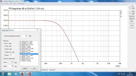
To generate a target, just select “Generate Target Response” from the Overlay menu in the FR window as shown attached. It only takes two shakes of a Lamb’s tail and it’s done. Hope this helps.
Peter
Hi Peter
Why Q 0.5 when use band pass or high+low pass for Target curve?
Hi Steve,
The low pass filter section of an LR4 crossover is made from two Butterworth second order (BW2) low pass filter sections. The Butterworth filter has a Q = 1/sqr(2), so when 2 of them are connected in cascade to form an LR4, the combined Q = 1/sqr(2) x 1/sqr(2) = 0.5.
Please note that the Q of a 2nd order filter uniquely defines its magnitude and phase relationship and therefore an LR4 crossover cannot be constructed from a Q combination of 1 x 0.5 for example, because the unique magnitude/phase relationship will not be maintained. Hope this helps.
Peter
Hi Steve,
Can you take your curve in post #96 and generate the target curve I show in post 98 and post result. Don't worry about the other types of target curve at this moment.
Peter
Can you take your curve in post #96 and generate the target curve I show in post 98 and post result. Don't worry about the other types of target curve at this moment.
Peter
Attachments
Last edited:
The Butterworth filter has a Q = 1/sqr(2), so when 2 of them are connected in cascade to form an LR4, the combined Q = 1/sqr(2) x 1/sqr(2) = 0.5.
Rubbish! (Sorry I just love saying that saucy phrase). I want to point out that there is no such thing as "combined Q" for a fourth order filter. Up to that point, you got it right PLB. The "Q" is inversely proportional to the "damping" and is a characteristic of second order functions only. The "Q" value describes the behavior where the filter enters the transition band (e.g. where it starts to "roll off" in the common parlance). I'm sure you know that PLB, that's noted for others who are reading this post.
The Linkwitz-Riley fourth order filter is formed from two second order Butterworth filters, connected in series and having the same corner frequency as the desired LR4 corner frequency. So, that's two second order Q=0.707 filters with identical corner frequency.
Since I'm 77 years old, I have been well aware of the fact that Q is a parameter exclusive to 2nd order systems for over 50 years, so I doubt you can tell me anything about them.
I chose to use the term "combined Q" because I was trying to provide Steve2111 an understanding for the term "Q factor" in the "Generate target response" menu which only has a single value entry for multi order filters!
Got it Charlie!!!
If you have a problem with that then I welcome your input on how you would describe the single entry for the "Q factor" when applied to filters of up to 6th order. Alternatively, chat to Ivo Mateljan.
And BTW Charlie, your childish comments do you no credit. (sigh).
I seem to be more confused as this "progresses". I'm concerned about phase which I have ignored upto now.
Going back to measurements:
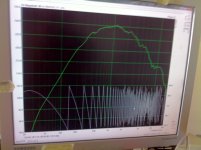
In my post Nº56 I included some measurements ( which look nothing like the manufacturer's ). Could it be my mic, Dayton emm6 or interface Focusrite Scarlett Solo? Or me?
The woofer measurement was nearfield, no xo's no filters, other speaker channels muted
The Mid measurement was nearfield, no filters etc. others muted.
The Tweeter measurement was farfield, xo's were applied. Other speaker channels were not muted. The tweeter channel had LR4 Highpass at 2KHz
Are these measurements for Woofer, Mid and Tweeter enough? Or should I do Tweeter (near or farfield) with other channels muted?
Going back to measurements:
In my post Nº56 I included some measurements ( which look nothing like the manufacturer's ). Could it be my mic, Dayton emm6 or interface Focusrite Scarlett Solo? Or me?
The woofer measurement was nearfield, no xo's no filters, other speaker channels muted
The Mid measurement was nearfield, no filters etc. others muted.
The Tweeter measurement was farfield, xo's were applied. Other speaker channels were not muted. The tweeter channel had LR4 Highpass at 2KHz
Are these measurements for Woofer, Mid and Tweeter enough? Or should I do Tweeter (near or farfield) with other channels muted?
If your woofer, midrange and tweeter responses are follows the desired slopes (now LR4 for easy understanding) then you have a good phase relationship between your drivers, you only need to adjust the timing (delay) of the drivers from here if needed.
So you need a tweeter only measurement too, to ensure it follows the LR4 slope.
So you need a tweeter only measurement too, to ensure it follows the LR4 slope.
Since I'm 77 years old, I have been well aware of the fact that Q is a parameter exclusive to 2nd order systems for over 50 years, so I doubt you can tell me anything about them.
I chose to use the term "combined Q" because I was trying to provide Steve2111 an understanding for the term "Q factor" in the "Generate target response" menu which only has a single value entry for multi order filters!
Got it Charlie!!!
If you have a problem with that then I welcome your input on how you would describe the single entry for the "Q factor" when applied to filters of up to 6th order. Alternatively, chat to Ivo Mateljan.
And BTW Charlie, your childish comments do you no credit. (sigh).
I was initially a bit upset reading your reply. That struck me as a bit crass for a gentleman of your generation but maybe I was asking for it. In all honesty, my post was intended to be tongue in cheek and I did not intended to offend you.
But now that I have thought about the "overall Q" concept I have some unanswered questions.
The only way I can see how the concept of a single Q can be applied to higher order transfer functions is through the concept of "overall bandwidth" eg of a bandpass function. Through a sort of "communicative" property you can express any 2*Nth order transfer function having N individual Q values (of each of N second order functions) as having the same overall response as if all N Q values took on the a value such that, when they are multiplied together, the product is the "effective" Q. You did this in your post for the LR4 filter, for example.
For a 4th order TF (product of 2 second order functions) Q appears twice and each could have different values, which seems a bit ill-defined to me because any pair of values could be used as long as their product is the overall Q.
For an example, the 8th order LR filter has four 2nd order sections, two with Q=0.54 and two with Q=1.31. It's two fourth order Butterworth filters in series. Multiplying all four Q values together give you... 0.5. Hmmm, seems like we are on to something here. So, every LR filter will have an "overall" Q of 0.5, or so it seems. Likewise, the 8th order Butterworth filter is formed using four second order filters with Q values of 0.51, 0.60, 0.90, and 2.56. Multiply those together and you get 0.707. The "overall" Q is the same as the second order one. Interesting.
But then the question that pops into my head is why these particular and different Q values are chosen for the second order stages of higher order filters instead of a value of (overall Q)^1/N? Is this a leftover from analog filter circuit design where you want increasing Q values so that the last stage with the highest Q value will overload (first)? I would be very interested in some insight about this issue.
Higher order "named" filters are often targeting a particular time or frequency domain response characteristic. "Butterworth" filters are "maximally flat" for example. Somehow the various Q values must have been prescribed so that these filters could be constructed. How that came about would be very interesting to know.
OK, I will do tweeter mesurement, but with High Pass LR4 at 2KHz. See what happens?
I presume Farfield?
I certainly don't want to be patronizing or offend anybody. I have noticed that with emails, or in this case posts, that it is difficult to joke as missing are facial expressions and voice intonations which give clues as to whether someone is joking or not. I'm sure everyone with knowledge wants to pass it on and those of us without want to learn. I certainly do. I thought flat freq was enough. Now realize there is Phase and Q's to learn.
I thought that if drivers are wired with the same polarity, they were in Phase? I now realise that adding Filters, XO's etc. they distort the Phase? Is that so? If you see my post Nº 48, Phase is plotted. I don't know how to read this graph, but zigzagging all over the place cannot be right?
I read somewhere, something like 2 LR4's at same freq, 360 out of Phase? So I gather that if one was delayed they could be aligned????
So summing up:
Tweeter measured farfield?
Is it filters that alter phase?
Can Phase be corrected? With delay or AllPass filters?
Hope these questions are not too dumb
Measure tweeter gated farfield.
Filters does change the phase. Only FIR filters does not change the phase.
If the drivers follow the LR responses the phases are corrected automatically to each other because phase is related to frequency response with minimum phase (not FIR) filters.
You correct the timing (with delay) of the drivers to align their phases at the desired axis.
LR4 filters are out of phase 360, which means one cycle delay to the lower freq driver, that's why you connect the drivers with same polarity, you can correct this only with FIR filters.
LR8 are out of phase 720 which means 2 cycle difference between the drivers, this may be audible.
Last edited:
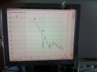
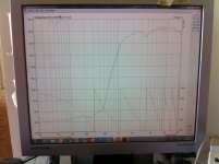
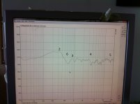
Done Tweeter Farfield Gated no filters except LR4 HighPass
Also attach previously posted Woofer only, no filters Nearfiels
And Mid only, no filters Nearfield
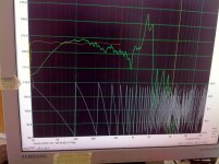
Then previously posted Farfield Gated Woofer, Mid, Tweeter with tweeter and woofer shelves
And today's Farfield all drivers with XOs and shelves but reduced Woofer gain
Also attach previously posted Woofer only, no filters Nearfiels
And Mid only, no filters Nearfield
Then previously posted Farfield Gated Woofer, Mid, Tweeter with tweeter and woofer shelves
And today's Farfield all drivers with XOs and shelves but reduced Woofer gain
Attachments
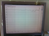
Ok, that tweeter response is clearly not looks like a 2kHz LR4 curve. A target response overlay would be very helpful here.
For example: 2kHz LR4 is -6dB at 2kHz and -24dB at 1kHz. You have around -4dB at 2kHz and -10dB at 1kHz, but the overlay can show the exact response you need.
Without overlay, good luck to create a 2kHz LR4 response from this, especially if you don't want to run the tweeter without xo filter (flattening-first method).
A farfield gated measurement for the midrange would be more useful than a nearfield response in my opinion, because of the high frequency limit of the nearfield measurement.
Last edited:
- Status
- This old topic is closed. If you want to reopen this topic, contact a moderator using the "Report Post" button.
- Home
- Loudspeakers
- Multi-Way
- Freq measurements and Hypex Filter Design adjustments