
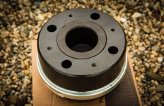
Both JBL and RCF have developed phase plugs with coherent/curved/optimized geometry.
These look like really nice drivers. Can we just purchase drivers? JBL ones?
These look like really nice drivers. Can we just purchase drivers? JBL ones?
Those vintage 476Be drivers were developed during the final chapter of JBL's "golden era" that started with the Hartsfield and Paragon.
All the experienced engineers have left the company since the takeover by Samsung.
However, you could still buy a set of 2450/51 drivers - with the same coherent wave phase-plug, and replace the diaphragms with Truextent Be samples. Output in the top octave will be limited though and you might want to add a tweeter. Marco Gea's 3 way with JBL 2450J Be drivers is an example.
I won't pollute this thread with extensive historical disquisitions, but there's often a lot to learn from history. This is, by the way, irrefutable and absolutely true for the current situation in the world.
The 1" RCF drivers were co-developed by engineers that left RCF to start 18Sound. The similarities between the N(S)D1090/95 and this driver are obvious. However, for whatever reason - probably related to costs and intellectual property, they came up with their 3P plug which is basically a combination of Hendricksen's Tangerine and circumferential phase plugs.
On a foreign forum there was a similar discussion about phase plug technology:
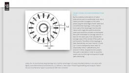
"When Clifford A. Henricksen of Altec Lansing presented his Tangerine phase plug in 1978, what he presented was not a little ingenious. It later turned out that he made some minor mistakes, but there is nothing wrong with the basic principle. But if we take a look at the current errors, we can better understand why Eighteensound has made the variant they have.
When the Tangerine phase plug (later also used as a designation for KEF's phase plug on the coax driver, without comparison otherwise), there were two relatively small errors that were probably not known.
One was that the transition from membrane side to exit side of the phase plug consisted of 4 flat sides for each channel. What one should have is a transition that is evenly expanding either conical or exponential, or cylindrical. The tangerine phase plug was none of the parts. The four straight sides, where two have an increasing distance, while the other two have a decreasing distance, give the largest cross-section in the middle of the course. This is relatively easy to figure out and it is not so surprising that they made such a banal mistake. It may be that they were aware of the cross section, but were not aware of the effect it has. In any case, we get something reminiscent of a parabolic process, and such processes give filter effects you definitely do not want in a driver who has to work high in frequency.
The second error was somewhat more complex to deal with, and according to the conditions of the time and the tools available, it was very complicated to calculate. In short, the largest Tangerine phase plugs had such long slots that they required a waveguide approach at high frequencies. When a channel is small enough, typically below 0.5 wavelengths, it will increasingly behave like a tube that only transports pressure waves. However, when the channel has a dimension that is over 0.5 wavelengths over a relatively large area, as is the case with the Tangerine phase plug, one will be completely dependent on being able to control the shape of the wavefront as well.
When you had the problem of transition in cross section as described in the previous section, ergo an effect that affects the wavefront, and in addition had such wide gaps that it was required that you take into account just this, you got an end product that did not deliver exactly what you had envisioned. Out of the phase plug, the wavefront was reasonably stable and not too frequency dependent, but things happened inside the phase plug which were partly unfavourable.
Several attempts have been made to combine the two. Eighteensound is mentioned, they have combined a ring with a series of short slits, all of which are within the maximum dimensions. Combinations of long and short radial slits have been tried, as well as pinholes in combination with half-long slits. Common to them all is that they can make a phase plug behave fairly calmly reasonably high in frequency, but they do little or nothing with the wavefront after the compression driver. We must not forget the work JBL has done with its coherent wave phase plug. This is something that disappears as soon as you go for one of the above mentioned variants. Even the Faitalpro 1440 lacks this essential feature to control the shape of the wavefront precisely."
Attachments
Last edited:
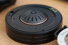
my picture present nd950- 1.4. Jzagaja knows plug dimensions
The ND950-2.0 with the black snout removed should be similar to the ND950-1.4.
Attachments
![rcf-nd950-1.4-compression-driver-[2]-3102-p (1).jpg](/community/data/attachments/861/861370-b69bd716e4e8410371d0f2f4490a15c8.jpg)
running variations on a working ath.cfg file and got a crash -
Mesh.AngularSegments = 96 ; crashes if reduce to 48
screen capture:
Ath 4.7.0
--------------------------------------------------
Freeware version for personal non-commercial use
--------------------------------------------------
-destination directory: D:\Audio\ATH\Horns\Rect400sh
-initializing
-fixed length: 145 mm
-calculating profiles
-morphing to rectangle
-morph: adding 24 mm in width
-morph: adding 12.5 mm in height
-fixed length: 145 mm
-stretched to boundary: dx=0 dy=0
-writing ABEC project
-writing geo file bem_mesh.geo
-final mesh average throat angle: 7.000 deg
-matched wavefront radius: 104.21 mm
terminate called after throwing an instance of 'std: ut_of_range'
what(): vector::_M_range_check: __n (which is 48) >= this->size() (which is 48)
D:\Audio\ATH\Ath-4.7.0>a
.cfg file attached as txt
Mesh.AngularSegments = 96 ; crashes if reduce to 48
screen capture:
Ath 4.7.0
--------------------------------------------------
Freeware version for personal non-commercial use
--------------------------------------------------
-destination directory: D:\Audio\ATH\Horns\Rect400sh
-initializing
-fixed length: 145 mm
-calculating profiles
-morphing to rectangle
-morph: adding 24 mm in width
-morph: adding 12.5 mm in height
-fixed length: 145 mm
-stretched to boundary: dx=0 dy=0
-writing ABEC project
-writing geo file bem_mesh.geo
-final mesh average throat angle: 7.000 deg
-matched wavefront radius: 104.21 mm
terminate called after throwing an instance of 'std:
ut_of_range'what(): vector::_M_range_check: __n (which is 48) >= this->size() (which is 48)
D:\Audio\ATH\Ath-4.7.0>a
.cfg file attached as txt
Attachments
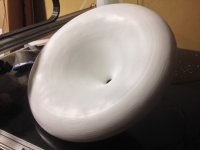
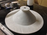
60cm sand horns are almost complete, just a little more putty and sanding to go on the front roundover. Fabrication done by Jzagaja. I'll start a build thread for the complete system soon.
Attachments
Mindsource - they look incredibly well made. Nice job.
In mine, I brought the back of the waveguide back on a cylinder larger than the driver. This gave a huge mounting surface to a middle plate of Lexan to bolt to each mating surface. I always worried about the mounting region because it is the thinnest (in your design, not mine) and will have the most compliance, so if it oscillates then that will be the weak point. This concern may not even be worthy of consideration these days because CDs have gotten so light that it likely doesn't matter - unless the driver is heavy, then it's an issue.
but some will probably say that they sound terrible But if they are accurate then who cares.
In mine, I brought the back of the waveguide back on a cylinder larger than the driver. This gave a huge mounting surface to a middle plate of Lexan to bolt to each mating surface. I always worried about the mounting region because it is the thinnest (in your design, not mine) and will have the most compliance, so if it oscillates then that will be the weak point. This concern may not even be worthy of consideration these days because CDs have gotten so light that it likely doesn't matter - unless the driver is heavy, then it's an issue.
but some will probably say that they sound terrible
But if they are accurate then who cares.In mine, I brought the back of the waveguide back on a cylinder larger than the driver. This gave a huge mounting surface to a middle plate of Lexan to bolt to each mating surface. I always worried about the mounting region because it is the thinnest (in your design, not mine) and will have the most compliance, so if it oscillates then that will be the weak point. This concern may not even be worthy of consideration these days because CDs have gotten so light that it likely doesn't matter - unless the driver is heavy, then it's an issue.
I had this exact same thought but with a cylindrical extension of the adapter to meet the cone. Not only for rigidity (The Beyma CD14fe is nearly 7.5lbs) but for a clamp to mount to as well. Albeit, there were some twists and turns in the design and build process and I'm just glad they materialized. For one example, the price of the material we used shot through the roof before we actually got the printer going.
I'm very thankful to Jzagaja for the all the effort he put in to make this happen. He really went above and beyond.
It certainly wouldn't be outside the realm of possibility to print an additional support / adapter or to wrap some bendable material around that area and pour a cast to address both points mentioned above. We'll see if it's needed once I have them up and going.
Last edited:
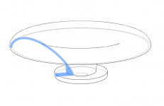
To have some fun and to encourage people to actually try a free standing waveguide, I decided to release my first "serious" design of this type (was already measured here some time ago with several drivers).
It is called ST260 (ST = Small Teaser), cca ⌀260 mm x 83 mm.
Throat entry angle is 19° and should work well with majority of 1" drivers.
STEP and STL files of the ready-to-print waveguide available: https://at-horns.eu/release/ST260.zip
Have fun and give us a feedback!
How do we think this would work with a BMS 4552nd with its 24º exit? Would the 24º exit into the 19º entrance warrant a redesign on the waveguide?
I think I have my delta printer, Flsun qqs w/260mm round build area, ready to print this in one piece.
I have no better advice than simply to try it. There's a lot of things going on in the top octave that we don't know in advance. It could be "redesigned" quite easily for a different throat angle but not necessarily with better results. It's not that easy, that's what I've learned so far. Overall, the exact angle match itself seems not that critical as I used to think.
Thanks, I'll look at that.running variations on a working ath.cfg file and got a crash - ...
Here's the STEP file for 30deg throat angle: https://at-horns.eu/ext/ST260-30.zip (259 x 81 mm)
Perhaps it could be a better match for drivers with wide exit angle.

Perhaps it could be a better match for drivers with wide exit angle.
Attachments
- Home
- Loudspeakers
- Multi-Way
- Acoustic Horn Design – The Easy Way (Ath4)