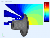
BTW, to view a pressure field, simply add this to the "observation.txt" file:
You will probably want to reduce the number of frequencies however, otherwise it will take quite a long time.
To see the throat in detail you can easily increase the resolution and limit the field area:
Code:
Nodes "FieldNodes"
  Scale=1m
  1  -0.2 0.3
  2  0.4 0.3

Field "F1"
  RefNodes="FieldNodes"
  EdgeLength=10mm
  BodeType=LeveldB; StepSize=3
  Range=60
  1 1 2
You will probably want to reduce the number of frequencies however, otherwise it will take quite a long time.
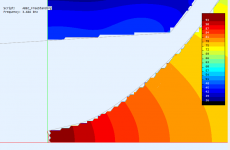
To see the throat in detail you can easily increase the resolution and limit the field area:
Code:
Nodes "FieldNodes"
  Scale=1m
[b]  1  0.0 0.2
  2  0.15 0.2[/b]

Field "F1"
  RefNodes="FieldNodes"
  [b]EdgeLength=3mm[/b]
  BodeType=LeveldB; StepSize=3
  Range=60
  1 1 2
Attachments
Last edited:
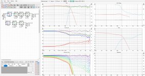
What crossover frequency would one want to use with this WG? My guess would be around 1200 hz to keep a smooth DI?As some start to print and measure the ST260, maybe it's useful to collect (again) the results so far - this is a courtesy of Pet007 who measured virtually the same WG before (maybe there was a tiny difference, I don't really remember), with three different drivers -
Just a note - the DI as shown is calculated from the front polars only (the only measured). The "real" DI will be closer to the simulations, where it is full-space.
This depends mainly on the compression driver used - what it can handle. Generally you want the lowest XO frequency possible with what you have. Then you simply choose a woofer size that makes a smooth overall DI. If we assume that most of the 1" drivers can handle 900 - 1000 Hz with ease, what should be the right woofer size for this, looking at the DI around this frequency (around 7 dB)? I don't know off the top of my head - maybe 12", maybe 10"... There is some freedom anyway.What crossover frequency would one want to use with this WG?
Last edited:
Now it would be great to have this measued to see if it's real to that extent. If it was, the whole system would "ring", i.e. there would be strong peak(s) in the frequency response and accompanying ringing in the time domain. Correctable with EQ but somewhat troublesome. What's interesting is that it has virtually no effect on radiation pattern.
I'll print and measure to see if it's a real problem and report back. It's printing now hopefully it doesn't crap out. It's 9hrs to print half. Hoping to have something to report soon...
Attachments
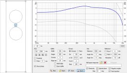
This is what I get from a simulation in Vituixcad. I simulated the diffraction-response from two 8" woofers on a 25x90 cm baffle. I SPl-traced the measurements of the ST260 + B&C DE502. And then I did some EQ'ing to get the responses flat.
Crossover is at 1000 hz LR4, this gave the smoothest DI. Note that the SPL-traced tweeter response only goes to 90 degrees, while the diffraction simulation goes 360 degrees.
Here is the dashboard from Vituixcad and below that the diffraction-tool.


Crossover is at 1000 hz LR4, this gave the smoothest DI. Note that the SPL-traced tweeter response only goes to 90 degrees, while the diffraction simulation goes 360 degrees.
Here is the dashboard from Vituixcad and below that the diffraction-tool.
Attachments
Last edited:
I'm holding my breath...It's printing now hopefully it doesn't crap out. It's 9hrs to print half. Hoping to have something to report soon...
")
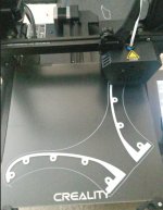
Ok you can breathe now The print split in the middle of the round over. So I'm thinking of making it thicker there and print with higher temp. See how it goes...
I'm new to 3d printing, if you guys have suggestions, please feel free.
It's been frustrating but fun at the same time lol
The print split in the middle of the round over. So I'm thinking of making it thicker there and print with higher temp. See how it goes...I'm new to 3d printing, if you guys have suggestions, please feel free.
It's been frustrating but fun at the same time lol
Attachments
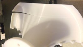
The print split in the middle of the round over. So I'm thinking of making it thicker there and print with higher temp.
Which material? This is typical for styrene materials. Try PETg, TPU (hard) or use filaments with fibers. Remedy can be closed chamber or draft/ooze shield.
At corners add circles one layer that prevent warping.
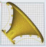
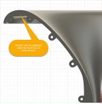
It looks really thin. Can we expect full simulated performance if the WG will resonate/vibrate substantially?
//
No
are you printing in PLA? I've done a lot with that. this kind of thing is pretty hard because all the plastic above is pulling up as it cools slightly. Is you bed material PEI? if not consider it, it has REALLY good adhesion.I'm new to 3d printing, if you guys have suggestions, please feel free.
It's been frustrating but fun at the same time lol
also you can make a flat "foot" like structure, it will help a lot too. just cut it off at the end. some people might recommend adding a raft to the print, but the problem then is that you wont get the nice smooth surface of the bed to glue the 2 halves together....
Which material? This is typical for styrene materials. Try PETg, TPU (hard) or use filaments with fibers. Remedy can be closed chamber or draft/ooze shield.
At corners add circles one layer that prevent warping.
I'm using PLA roll which came with the Creality CR6E I bought.
I place my camera light box on it. and bumped up the temp 205/60 and 50 speed. I'll add the circles, thanks for the tip!
are you printing in PLA? I've done a lot with that. this kind of thing is pretty hard because all the plastic above is pulling up as it cools slightly. Is you bed material PEI? if not consider it, it has REALLY good adhesion.
also you can make a flat "foot" like structure, it will help a lot too. just cut it off at the end. some people might recommend adding a raft to the print, but the problem then is that you wont get the nice smooth surface of the bed to glue the 2 halves together....
Yes PLA, just using the carborundum glass hotbed that came with it. I'll check on PEI and foot structure. Thanks
- Home
- Loudspeakers
- Multi-Way
- Acoustic Horn Design – The Easy Way (Ath4)