In the more than 10 years that I have been interested in horn technology - both historical and recent developments, there has been a (non-audio-related) dynamic phenomenon that seems to keep recurring across threads/forums.
Before making my point, I would like to refer - by analogy - to an adjacent technology about which I read a scientific paper last weekend, namely woofer cones.
Simply put, woofer cones come in different variations: paper, plastic, aluminum, etc. and in different shapes: conical and curved, with or without the addition of ribs. Combinations of these cone varieties are developed for specific applications, usually resulting in sub-optimal performance outside the intended application area.
In other words there's no such thing as one size fits all.
The same principle applies to horns (and waveguides). A horn that excels in some respects will be compromised wrt other properties and characteristics.
In the light of this thread, waveguides generally show superior directivity at the expense of loading, among other things. The latter is pre-eminently an aspect in which classical horn profiles excel.
From a purely objective point of view, a waveguide is not absolutely better in every respect than a classic horn, such as horns based on the JMLC principles.
Knowing this, its striking that in many threads about horns, animosity often arises with regard to these different horn types.
This has nothing to do with the horns themselves, of course. I have yet to run into the first heated discussion about woofer cones.
The 'heat' is purely a product of 'human nature', ego-induced behavior in short.
At a higher abstraction (metaphysical) level, it is precisely this mechanism that keeps humanity from real progression in today's world.
Let's rise above this.
An observer.
Last edited:
It seems from the results gathered so far that the actual contribution of HOMs (inherent to a profile) will be generally very low, at least up to a rather high frequency. I'm more and more convinced that what is observed as "disruption of pressure field" is almost always caused by a suboptimal mouth termination. Take any shape of the Salmon horn family and make a smooth termination e.g. via a clothoid and I'm sure it will all behave virtually the same. That's the reason I said it is "nothing more" than a smoothly terminated exponential horn. Because in my view there's really nothing more to it. I still may be missing something, but then show me.
HOMs will be low in the designs shown here, but they are the exception, not the norm. No contour that changes a flat wavefront into a curved one can do this without HOMs, so they always exist. But poorly designed horns will have lots of HOMs and reflections. To me, LMLC ideas of HOMs and mine are not the same.
But I do agree that the mouth transition will dominate the wave reflection, which cause HOMs as well as resonances. We seem to forget that a decade or more ago virtually all horns had large amounts of reflections. Today there are still too many.
BTW, this was a 10-minute work with Ath including the BEM run. Should anyone want to explore this breakthrough technology, here's the script.
This is huge at 951mm, is this ST260's big brother, the BIG Teaser?

Ro808 - I agree with you to some extent. The last part mostly. Here we have a very beemy horn with high "gain" - this can be desirable in some situations but maybe not in a domestic situation. So we can sacrifice some spl and optimise on directivity a bit more - thats good - horses for courses.
//
//
For one thing, a superior horn throat acoustical impedance characteristic loading the driver, due to the controlled expansion rate and the better impedance matching at the horn mouth resulting from the rollover inherent in the Le Cléac'h generated profile.
To me, that is an example of a very bad device owing to the large amount of reflections.
When I asked about the intention, I of course was interested in this claim: "... but they clearly work as intended." Clearly I would like to understand what was the intention and what was verified. The smoothness of the polars? Is that it?
Frankly, I see absolutely nothing special about the acoustical impedace you show. Somewhat suboptimal, at best.
Agreed.
And knowing Kolbrek well, I am not aware of any work of his that validated what is claimed.
But it is impossible to listen for a long time, it is tiring.
A very clear indication of a problem.
From a purely objective point of view, a waveguide is not absolutely better in every respect than a classic horn, such as horns based on the JMLC principles.
In what objective aspects are the waveguides developed here not superior?
For my money no work on horns/waveguides is even comparable to what has been done here. (Well maybe my own , but these are definitely an advancement on my work.) The designs are exemplary and if I were building a new design it would certainly use one of these devices. I find the idea that the older methodologies being discussed here are comparable to what Marcel has done to be an insult to him.
This is simply not true. An optimal design could excel at all characteristics that one wants. Not everything is a tradeoff. The designs here are not trade-offs except perhaps with size. Some are a little small for my taste. And while we may argue about what DI is best, Marcel's approach can achieve whatever DI one wants.
, but these are definitely an advancement on my work.) The designs are exemplary and if I were building a new design it would certainly use one of these devices. I find the idea that the older methodologies being discussed here are comparable to what Marcel has done to be an insult to him.A horn that excels in some respects will be compromised wrt other properties and characteristics.
This is simply not true. An optimal design could excel at all characteristics that one wants. Not everything is a tradeoff. The designs here are not trade-offs except perhaps with size. Some are a little small for my taste. And while we may argue about what DI is best, Marcel's approach can achieve whatever DI one wants.
Earl, thank you indeed for your supporting words, both here and in the recent podcast.
I'm far from understanding the physics involved and would never be able to do any analytic work (which I deeply admire) but I've seen enough to recognize when someone claims BS and it kind of irritates me. For the most part I just try to pass it but sometimes it's stronger than me.
I'm far from understanding the physics involved and would never be able to do any analytic work (which I deeply admire) but I've seen enough to recognize when someone claims BS and it kind of irritates me. For the most part I just try to pass it but sometimes it's stronger than me.
Last edited:
Measurements from a failed print job
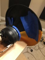
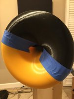
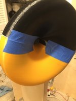
I took some measurements of the Peerless DFM-2535R00-08 (the only compression driver I have on hand) on a failed print job of the horn included in post #4948.
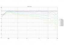
Basically, the adhesion failed at the very edges of the horn. In any case, I still was curious about the performance and just blue-taped the two halves (no epoxy, no glue, nothing) - just two sides taped together. So the horn should not be judged by the measurements included below (i.e. too many imperfections in the final assembly), but just wanted to share the results nonetheless. I just took quick 0 - 60 degree measurements (approximately 900cm @ 4ms gate time). I was pretty impressed - seems to reasonably match the results posted in post #4946, despite the imperfect print job.
I took some measurements of the Peerless DFM-2535R00-08 (the only compression driver I have on hand) on a failed print job of the horn included in post #4948.
Basically, the adhesion failed at the very edges of the horn. In any case, I still was curious about the performance and just blue-taped the two halves (no epoxy, no glue, nothing) - just two sides taped together. So the horn should not be judged by the measurements included below (i.e. too many imperfections in the final assembly), but just wanted to share the results nonetheless. I just took quick 0 - 60 degree measurements (approximately 900cm @ 4ms gate time). I was pretty impressed - seems to reasonably match the results posted in post #4946, despite the imperfect print job.
Attachments
Last edited:
I took some measurements of the Peerless DFM-2535R00-08 (the only compression driver I have on hand) on a failed print job of the horn included in post #4948.
Basically, the adhesion failed at the very edges of the horn. In any case, I still was curious about the performance and just blue-taped the two halves (no epoxy, no glue, nothing) - just two sides taped together. So the horn should not be judged by the measurements included below (i.e. too many imperfections in the final assembly), but just wanted to share the results nonetheless. I just took quick 0 - 60 degree measurements (approximately 900cm @ 4ms gate time). I was pretty impressed - seems to reasonably match the results posted in post #4946, despite the imperfect print job.
This looks like something I would do.
I salute you!
A very clear indication of a problem.
To me, this is one of the most notable things about the Summas:
When I bought them, I was single and I lived by myself in a giant house, and I worked at home. So I would have those speakers blasting all day and night at ridiculous SPLs. And they just don't get fatiguing.
It's a bummer that this is so hard to quantify. For instance, I've been to dozens of audio shows, and a lot of customers peek their head into a demo room, listen for ninety seconds, then leave.
In that kind of a scenario, it's basically impossible for the customer to evaluate how the loudspeaker will sound long term.
Here's a weird comparison:
Nearly all of my TVs have been purchased based on whether they are "a good deal." As I slowly move into my new house, I decided that I would *finally* get a TV that was well regarded by the reviewers. So I went down to Costco, and I came *this* close to doing what I always do, which is buy the TV that gives you the biggest screen for the least money. But I managed to resist that urge, and instead I bought a Sony that was top rated, and cost about twice as much as the competition. I got the TV home, and when I plugged it in, it was *marginally* better. But as I watched it, day after day, I began to appreciate the things it does well. After owning it for a couple weeks, my old/cheap TV is intolerable.
But until I owned a GOOD TV I was incapable of detecting what the difference was.
Last edited:
To me, that is an example of a very bad device owing to the large amount of reflections.
Just to clarify, I was thinking in comparison to an equivalent-sized Bessel, conical, exponential, hyperbolic-exponential, tractrix or spherical wave horn.
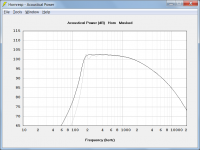
The black trace in the attachment shows the power response of the Le Cléac'h horn example used earlier. As can be seen, the ripples in the throat acoustical resistance do not significantly affect the power result. The grey trace shows the power response of an equivalent exponential horn.
Attachments
Last edited:
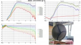
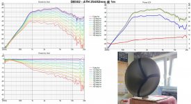
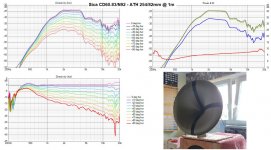
As some start to print and measure the ST260, maybe it's useful to collect (again) the results so far - this is a courtesy of Pet007 who measured virtually the same WG before (maybe there was a tiny difference, I don't really remember), with three different drivers -
Just a note - the DI as shown is calculated from the front polars only (the only measured). The "real" DI will be closer to the simulations, where it is full-space.
Just a note - the DI as shown is calculated from the front polars only (the only measured). The "real" DI will be closer to the simulations, where it is full-space.
Attachments
Last edited:
I took some measurements of the Peerless DFM-2535R00-08 (the only compression driver I have on hand) on a failed print job of the horn included in post #4948. ...... snip
Nice, if not fantastic
! What was the circumstances around the measurements... did you use EQ? Or probably normalised - can we see the actual raw FR?I mean this is +/-0,5 dB on axis between 450Hz and 20k - I suppose you have had to - please present the EQ curve. Also, at what spl was this? Can you extract distorsion out of your measurements - if so, please post some figures.
//
Last edited:
That was normalized, i.e. effectively an EQ used such that the response at selected angle (on-axis in this case) is exactly flat. It clearly describes the WG "alone", without the properties of a particular driver. In the Pet007's data this is the left lower chart. The upper left is the raw data.
- Home
- Loudspeakers
- Multi-Way
- Acoustic Horn Design – The Easy Way (Ath4)