mabat, Autodesk has just reduced the functionality of the free version of Fusion 360, the main sticking point being that step export is no longer allowed. This would make it hard to transfer between packages or give a file to a CNC shop. It certainly is a pain for what I have been using it for lately.
How hard would it be to get the curve import going on another CAD program?
How hard would it be to get the curve import going on another CAD program?
First, it must be a free (or cheap) program, otherwise it makes a little sense. I'm not an experienced CAD user so I don't know much about the possibilities in this area. Scripting language (as with Fusion) would by nice but not really necesary I guess, as long as it is possible to create the shape manually. If you are interested how it's done in Fusion just see the import scripts - nothing more than the commands available are used there. Basically it imports the splines and then uses the loft feature.
This seems like it could work to create to create the curves from the points files if the data was changed to the right format?
Macro WireXYZ - FreeCAD Documentation
Macro WireXYZ - FreeCAD Documentation
Autodesk has just reduced the functionality of the free version of Fusion 360, the main sticking point being that step export is no longer allowed.
Although unfortunate, this was to be expected. It's part the standard business model for commercial online software.
Last time I used Fusion was in 2017.
I replied to Autodesk's email and made the case that since .stl export is allowed for hobbyist 3D printers, .step should be allowed for hobbyist CNCers, as cheaper machines are making it more common as a hobby. Everyone who got the email should response supporting this, the sender did email me back so there is a real person on the other end reading replies.
Sure, I think you could try it right away
I think it can definitely be made to work in FreeCAD but my coding skills are right up there alongside my non existent maths skill
")
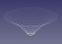
I can import all the points as a points cloud, and I was able to make a closed line from the xyz macro (the black line on the bottom of the point cloud). That only works for a single slice as is, so it's either 20 separate files and macros or I have to work out how to code it
Attachments
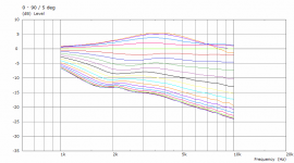
I have a question regarding the measurement of a compression driver output wavefront -
if we have a numerical prediction for some waveguide driven by an ideal wavefront (which is not a problem now), couldn't the actual source wavefront be calculated from the difference between the model and the measured far-field data of the DUT in the same waveguide?
For example, I could made a test setup with a smaller (axisymmetric) waveguide mounted into a sphere easily. This could be modeled and simulated with an arbitrary precision.
Last edited:
Good job! That's a good starting point. I didn't know about the Python scripting in FreeCAD - just anything should be possible with that. I will also give it a try, I only hope this will be the last time I have to learn some new CADI can import all the points as a points cloud, and I was able to make a closed line from the xyz macro (the black line on the bottom of the point cloud). That only works for a single slice as is, so it's either 20 separate files and macros or I have to work out how to code it
I have a question regarding the measurement of a compression driver output wavefront -
if we have a numerical prediction for some waveguide driven by an ideal wavefront (which is not a problem now), couldn't the actual source wavefront be calculated from the difference between the model and the measured far-field data of the DUT in the same waveguide?
For example, I could made a test setup with a smaller (axisymmetric) waveguide mounted into a sphere easily. This could be modeled and simulated with an arbitrary precision.
The answer is yes/no. What you suggest can be done but only if one has knowledge of the internal modes of the device. For example, with an OSWG one does know these functions (although they are quite complex) so such a thing could be done (but it is hardly the most effective way to do this.)
With a numerical simulation that does not conform to any of the separable coordinate systems one does not have the modal transfer functions readily available. I'm sure that they could be numerically calculated, but that's a lot of additional work.
Best is to use a PWT as we talked about before.
Ah, OK. I just wondered if a computational method could be devised where these unknowns would effectively cancel out - there would be two data sets where only the source wavefront would be different. From your answer I gather that's not possible.
That is, a method where the actual waveguide/device used would not be even a factor.
That is, a method where the actual waveguide/device used would not be even a factor.
Last edited:
But it is possible, has to be. It's just that this transfer matrix is not known "modally" in the numerical case, but it is in the analytical case, i.e. OSWG. But one could make up this matrix numerically by calculating the far field for each possible mode shape at the throat. You know the zeroth order one already, but you don't know the higher order ones.
If you expand the throat as a series of functions, all known in this case (Bessel functions), and then calculate the far fields numerically for each mode shape > 0, doing this for say the first four or five modes, then you would have the matrix that you need to back calculate the throat wavefront shape from the far field data. If that's what you want to do.
If you expand the throat as a series of functions, all known in this case (Bessel functions), and then calculate the far fields numerically for each mode shape > 0, doing this for say the first four or five modes, then you would have the matrix that you need to back calculate the throat wavefront shape from the far field data. If that's what you want to do.
- Home
- Loudspeakers
- Multi-Way
- Acoustic Horn Design – The Easy Way (Ath4)