So ok because the driver is strong enough (mechanical) for a 700 hz in hifi use : surmise less than 90 db average very confortble & most reccordings :7 to 8 db more average dynamics raises max? so less than 100 dB at highest peaks for most hifists at home but rare good classical reccordings that don't have loudness mixing - and in relation to the average spl 90 db listening level, most reccordings, most dacs (amps) noise floor ! -
Is it a good reading of your input, please - sorry for the noob input level - pun-here-? Often difficult to read correctly the datasheets for a simple enthusiast...
Is it a good reading of your input, please - sorry for the noob input level - pun-here-? Often difficult to read correctly the datasheets for a simple enthusiast...
Last edited:
Slightly off-topic - I've just ordered new Faitals HF1440 for €225/piece. Hope they are worth it!")
Nice!
I'm sure they are worth it.
You've ordered here, I assume?
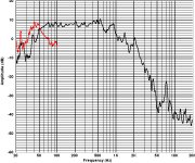
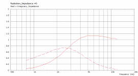
They say 700 hz but watching the impedance curve, 700 hz is 40 ohms... are they not a little bit optimist and should have said 900/1000 hz cut-off for this driver
I wouldn't hesitate to use this driver from 600 Hz and 450-500 Hz is probably ok, as is for it's smaller brother, the HF200.
The HF1440 has a 3.4" diaphragm compared to 2.91" of the HF200.
Impedance plots are a bad indicator of compression driver capabilities.
Some people use this 1", crossed at 800 Hz for livesound applications at very high SPLs:
Attachments
Last edited:
... So better the HF1440 so to speak about the trebles and low end in hifi use ?
Ah, 500 cm width horn for them ?
Edit : 2 ways possible with a low Le bass driver with circa 35 Fs driver, circa BR 45 hz tuning, rephrased such low pass/compression drivers in the right horn are XO proof with a 15" in the cut-off area : let be crazy : 500 to 700 cut-off?
Ah, 500 cm width horn for them ?
Edit : 2 ways possible with a low Le bass driver with circa 35 Fs driver, circa BR 45 hz tuning, rephrased such low pass/compression drivers in the right horn are XO proof with a 15" in the cut-off area : let be crazy : 500 to 700 cut-off?
Last edited:
A bit of a rookie question...why be worried about impedance, even down to 500Hz?
That's correct, I was mostly thinking about excursion. Impedance is virtually irrelevant.
how is it working between the impedance top peak and its lower upper feet : is there not an acoustical short-cut here created by the driver resonance materialised in the impedance peak, so spl loss ?
Or it's irrelevant because we want to use such datas with low mechanichal constraint -hifi use- i.e. the amp can manage it as far we can deal with distorsion and if X-mech is not reached?
Or it's irrelevant because we want to use such datas with low mechanichal constraint -hifi use- i.e. the amp can manage it as far we can deal with distorsion and if X-mech is not reached?
Edit : 2 ways possible with a low Le bass driver with circa 35 Fs driver, circa BR 45 hz tuning, rephrased such low pass/compression drivers in the right horn are XO proof with a 15" in the cut-off area : let be crazy : 500 to 700 cut-off?
That's what I am focusing on.
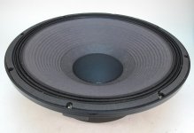
The HF1440 combined with either 15PR400, 15FH500, 15FH510, or 15FH520 are proper ingredients.
Beyma offers similar drivers.
I'm currently looking at subwoofer drivers with a smooth roll-off.
Some say you need a curvilinear cone for mid-range reproduction rather than a straight one, common with subwoofer drivers.
I'll leave it at this, before I drift off-topic.
Last edited:
Very fast : seems most of 15" Beyma have stifer cut-off below 1 hz...at least often ! Instinct which has nothing to see with knowledge says to me the woofer should be a little horned both to better tmatch the horn profile, match time horizontal starting point around cut-off while with the bafle step & all I don't know. My feeling it should has a the lowest Le/1 khz and a solid amp to control it in order to try to match the cd/horn... Faital 15HF250 seems to be stronger than the 15pr400 while having a worsr Le. Some says a good 15" EV with higher Fs and worse datasheet is more lively and better sounding...  ...
...
I believe to remember Earl G was using very stiff and heavy cone but nuclear motor (high BL)... but eventually in the Suma with multiple distributed sub if the cut-off was too high in the Suma big cabinet if very huge rooms?!
Ok, off-topic, let- you guys focus on the horn shape + cd combo, already hard to follow for me...
...I believe to remember Earl G was using very stiff and heavy cone but nuclear motor (high BL)... but eventually in the Suma with multiple distributed sub if the cut-off was too high in the Suma big cabinet if very huge rooms?!
Ok, off-topic, let- you guys focus on the horn shape + cd combo, already hard to follow for me...
Regarding woofers, it's all about the frequency response in the end, which is normally no issue if used only up to 500 - 700 Hz. So it boils down to basic directivity and the total Q at resonance (may be important for passive crossovers, irrelevant for active). Efficiency and power dissipation capability is more than good enough with these drivers. That's about it.
Last edited:

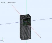
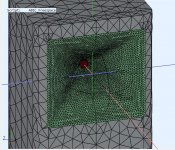
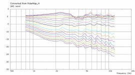
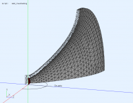
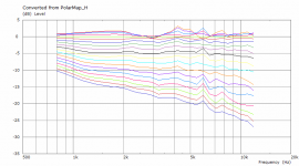
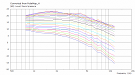
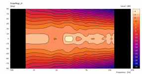
So, here is a comparison of a flat and "fully modeled" rear side of a free standing waveguide. Axisymmetric, ⌀300 x 100 mm.
Flat rear side:
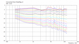
Fully modeled rear side:

Flat rear side:
Fully modeled rear side:
Attachments
That's correct. No other plans at the moment.mabat,
if i'm not mistaken currently the only supported shape for throat entrance is circular, right?
So, here is a comparison of a flat and "fully modeled" rear side of a free standing waveguide. Axisymmetric, ⌀300 x 100 mm.
"Flat" implies the horn mouth without anything behind it?
Last edited:
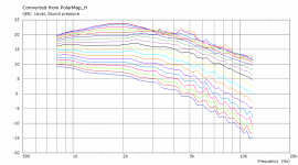
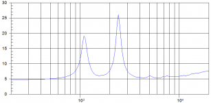
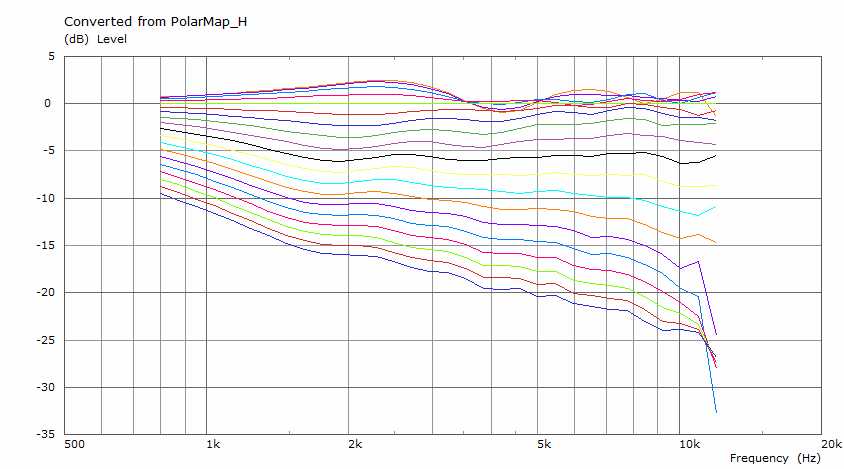
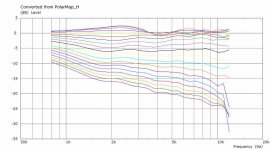
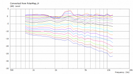
A bigger still - ⌀360 mm (q from 0.995 to 0.999). Now it would be helpful being able to measure the real thing. Although noticeably smoother, there are still apparent some high Q resonances and I wonder how real they are.
The last two examples are for a modeled rear side.

The last two examples are for a modeled rear side.
Attachments
Thanks, that explanation somehow eluded me.
A bigger still - ⌀360 mm (q from 0.995 to 0.999). Now it would be helpful being able to measure the real thing. Although noticeably smoother, there are still apparent some high Q resonances and I wonder how real they are.
The last two examples are for a modeled rear side.
Perhaps ⌀450 mm leads to a further reduction?
It's not that better. Obviously, the axial symmetry is still detrimental to axial response.
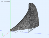
Now the interesting part will be to find a way how to make it better still, without losing the directivity too much.

Now the interesting part will be to find a way how to make it better still, without losing the directivity too much.
Attachments
- Home
- Loudspeakers
- Multi-Way
- Acoustic Horn Design – The Easy Way (Ath4)