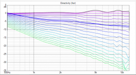
I think that avareging the responses around the axis (in the "listening window" for the direct sound) would make even better picture. Otherwise it may be difficult to chose to right axis for the DI comutation because of the possible diffraction - can be misleading easily.
Well, I shall correct this statement before I get correctedWith OS waveguides the design axis is typically somewhere more off-axis, like 20 deg or so - depending on how much ripple there is right on axis")
The primary reason for this is of course the toe-in and the time/intensity compensation for a wider sweet spot (and apparently it works!).
I think that avareging the responses around the axis (in the "listening window" for the direct sound) would make even better picture. Otherwise it may be difficult to chose to right axis for the DI comutation because of the possible diffraction - can be misleading easily.
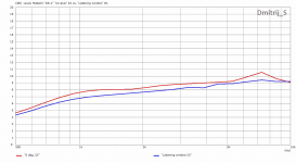
I would not say that there is a very big difference in "on-axis" vs "Listening window" DI. At least the difference is much more less profound than that between the different horns.
I took the curves for "Listening window" as described in CTA-2034-A.
Code:
Listening Window
The listening window curve is a spatial average of the nine magnitude responses in the ±10º
vertical and ±30º horizontal angular range.
•  0°
•  ± 10º vertical
•  ± 10º, ± 20º, ± 30º horizontal
Attachments
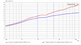
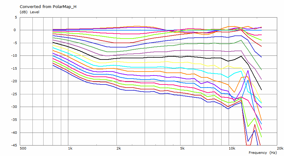
Dmitrij, if you look at the power response curves, can it be said that there's a particular polar response curve in each case that is the most similar in general? I suspect there is and it would be probably dependent on the overall beamwidth but it could give a useful hint when looking at the polar data alone, without the need to calculate the DI curve(s).
- From my VituixCAD example above this is the power response:
Here it best matches a polar curve at about 30 deg:
- From my VituixCAD example above this is the power response:
Here it best matches a polar curve at about 30 deg:
Attachments

Last edited:
Here you go. Would you consider it "more CD"? I'm not sure I would.
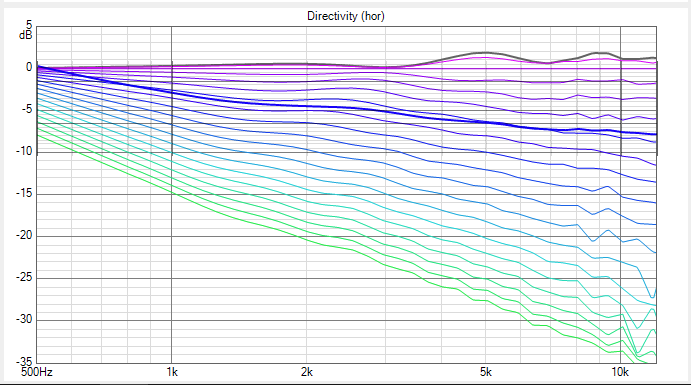
It is clear that reducing the flare radius is not a good idea - and this was already too much, IMHO. I could have told you right away but you wouldn't believe me
Yeah I would consider this more cd, since the 1.5k range is much more in line with the higher part ( look at the black -10dB curve.
This specific sample is not so good, I didnt check anything, juat wanted to show that with changing the curve of the second part of the horn, you can use the diffraction " waistbanding " effect to match the lower part of the spectrum more to the higher part, rhus making it more cd. In practice a bigger flare will of course always be better. Its a juggling act.
It kind of surprised me, I expected bigger problems.Once again, thanks for the sims.
It seems the free-standing axisymmetrical variants have potential.
For me CD means that a shape of radiation pattern doesn't change with frequency, or at least that it smoothly and mildly narrows as frequency rises. It the example above it gets narrow at 2 kHz and then widens again at 6 kHz (not to mention the narrowing above 12 kHz). This is just not more CD to me - I would prefer the overall gradual DI rise anytime.Yeah I would consider this more cd, since the 1.5k range is much more in line with the higher part ( look at the black -10dB curve
Last edited:
It kind of surprised me, I expected bigger problems.
There's probably room for improvement, but these initial attempts - once materialised - would likely perform well and look good too.
As said; this specific example is not really good and I would never use it like this, but with some juggling you'll get the hf well behaved and still can have the -6 and -10 line be constant down to the lower frequencies.
Maybe its because I normally design horns for PA purposes that I find this more important, I always strive for a good balanced stereo image if one stands way out the middle , in my experience you can not achieve this with a response which is down6dB at 8k compared to 1.5k.
I look at it this way; if you can achieve +-2dB over the whole horn range over the whole adience area, you arw doing a good job.
Cheers
Last edited:
The larger and more gradual the termination flare becomes, the better the individual curves look (especially near the axis), but at some point the pattern starts to widen at the lower end of the passband. Obviously, the result is that the DI starts to tilt.
The interesting question is what is more important subjectively – really flat DI or extremely consistent frequency response within the listening window?
The interesting question is what is more important subjectively – really flat DI or extremely consistent frequency response within the listening window?
Last edited:
The curved baffle is undoubtedly effective and the final design probably required quite a few simulation hours.
Link to LS50 whitepaper: https://www.shop.us.kef.com/pub/media/wysiwyg/documents/ls50/ls50_white_paper.pdf
"A variety of geometries, ranging from rectangular enclosures to more complex shapes, were analysed and the axial frequency response of idealised mid-range and high-frequency drivers evaluated. The geometry was refined over a number of iterations to produce the smoothest response in the hemisphere in front of the loudspeaker"
@mabat - would love to see an ideal CD design for a 1.5" driver down to 600 Hz to mate with a 15" woofer for a two way...
OK but this is inevitable, sooner or later. In a standard monopole box there's no way around that, the DI will fall - I really prefer the overall gradual rise than the more abrupt one, which is then typically around 1 kHz.What kessito is describing is the trade-off I was trying to balance with my design. The larger and more gradual the termination flare becomes, the better the individual curves look (especially near the axis), but at some point the pattern starts to widen at the lower end of the passband. Obviously, the result is that the DI starts to tilt.
Last edited:
Working on just that.@mabat - would love to see an ideal CD design for a 1.5" driver down to 600 Hz to mate with a 15" woofer for a two way...
A freestanding one, to be precise.- Home
- Loudspeakers
- Multi-Way
- Acoustic Horn Design – The Easy Way (Ath4)