Thanks Kees -- appreciated.
I tend to feel a bit like you about the '100 years of horns' dialog weaving through this thread.
But IMO the audibility of horn distortion is relevant to the goal of this 'design project' thread. Do the designers ignore it as being unimportant (Dr Geddes), or do they set a target and meet it (others)?
If your wish for an integral phase plug is to be pragmatically achieved, I assume the idea is to 3D-print the whole thing and make it available to hobbyists, and fit it to a designated compression driver with its integral phase plug removed?
P.S. I half expect some brands design their drivers and horns integrally, instead of independently on the assumption of a common wavefront at the interface. I use at home 18Sound with their 3P phase plug and ESS horn technologies, and IMO they would have been developed in turn using the other as test beds.
Last edited:
What I would love to be the outcome of this thread, with all these bright minds united, is a waveguide with a custom phase plug ( maybe as a replacement in an excisting compression driver) which has a great constant directivity behaviour for at least 4 octaves without using diffraction mechanisms where the bias is much more put on sound quality instead of maximum output compared with excisiting solutions ( phase plug much more focussesd on great wavefront coherence than high compression/ cheap to manufacture)
IMHO, for this goal is is nessecary to;
1- do all simulations in a finite baffle, since this matters a lot, not only for the lower frequencies,
2- to simulate the complete system starting with the phasing plug,
3- build and test promising designs to validate and improve the model.
There was a moment in the past I had the same goal in mind, as you know. Two things have lowered my excitement however - first, there will always be deficiencies in the mechanical parts of a driver that are out of control (at least out of my control) that would spoil the effort anyway, and second, I somehow feel that what is currently possible with "ordinary" stock drivers is already good enough. Frankly, I'm afraid this would lead to only a marginal subjective difference in the end. So is it worth the effort (mainly the manufacturing part as the design part may be fun and easy)? I don't know but I wouldn't bet on that.
What I can do and will do for sure are the first two points on your list, I'm already working on that - this is the easy part. I can make the tools available, extending the functionalities of what I already have, only leaving out the mechanics of the diaphragm as this is something I can't do.
All, as for the nonlinear stuff, please let's make clear once and for all that in horns, including compression in drivers, there's no audible nonlinear distortion to worry about. It is so low order that this is just non-issue. Since this thread is concerned with waveguides, please don't address all possible and measurable sources of distortion in drivers in general, we can't do anyting about it here anyway.
That was a good rant, Kees

Last edited:
Sure, but that's not a spherical wavefront anymore, as the dome moves axially, not radially. You are right that even an axially vibrating dome can work surprisingly well in a conical horn, however, I know that. Maybe just not so low in frequency as I woud like to get - as with large format compression drivers. That's what I'm aiming at.
The direction of motion is not that important. Sound is not a result of the motion itself, but it is a result of the pressure which in turn is a result of the acceleration. Sound waves may escape in any direction, but as it is backed up by pressure evenly distributed along the dome shape, it will give a fairly controled wavefront.
The shape of the wavefront is very much dependent on how hard the diaphragm material is (relative to its mass off course). But as for compression driver, at some point the relative amount of errors will overcome the near perfect spherical wavefront.
But as you point out, it is not easy to get a decent result at lower frequencies with a diaphragm that small.
If you had an axially vibrating hemisphere (like in a dome tweeter), the acceleration would be maximum at the apex and actually zero at the rim, which makes the whole situation very different to a simple spherical radiation where the acceleration is the same accross the whole surface. This would make quite a difference at short enough wavelengths, wouldn't it.The direction of motion is not that important. Sound is not a result of the motion itself, but it is a result of the pressure which in turn is a result of the acceleration. ...
In general, if the amount of odd harmonics is low, THD is usually low.
That depends on what causes distortion in the first place. For BL(x)-related artifacts, it is often the case.
IMD is bandwidth and excursion related (among others) and as such much more of a problem for direct-radiating cone drivers than for compression-loaded smaller diaphragms.
If your point is that THD in compression drivers is not followed by IMD, I see no reason for that to be true at all. For sure, the mechanisms causing THD in DCs typically are a bit different from the mechanisms causing both THD and IMD in a small woofer, but that does not mean the mechanisms causing THD in a CD does not also cause IMD in that same CD.
Many modern so-called high-end tiny cone woofers that should cover 30-5000 Hz suffer from relatively high amounts of IMD despite relatively low THD.
IMD is the most troublesome type of distortion imo, but is often overlooked.
I think that is a bit of an understatement.
If you had an axially vibrating hemisphere (like in a dome tweeter), the acceleration would be maximum at the apex and actually zero at the rim, which makes the whole situation very different to a simple spherical radiation where the acceleration is the same accross the whole surface. This would make quite a difference at short enough wavelengths, wouldn't it.
If you have an axially vibrating hemisphere that would be true, but dome tweeters are not hemispheres, they are typically far less than that.
I happen to have the data for a 75mm compression driver dome in front of me right now, it has 58mm radius of the profile, which means a full hemisphere would be 116mm, and the angle between a flat diaphragm and this dome will be 37 degrees maximum.
Another important thing is that as we calculate the total Sd of this driver, we do not include its entire surface area, we only include what is normal to its axis. So if the dome was in fact a hemisphere, it would not radiate sound at its very edge, but at the same time, that would not be a significant part of the calculated radiating area either.
The sound pressure for a given diaphragm area (actual area) will be very low if the angle is very high. At the same time, it will be equal to its portion of radiating area calculated as normal to its axis of motion.
So looking at the above factors, it is clear that in order to keep SPL equal around the entire dome, it is also important for a waveguide to terminate the edge of the dome properly.
In other words, the spherical wavefront of the dome will be a bit more flat than the dome itself, and if the dome has no waveguide to back it up, the spherical wavefront will collapse from the outside edge.
Kees, this seems to be an excellent (project) proposal.
A custom phase plug has recently been investigated. I assume that you are especially interested in these kind of matters?
+1
//
PDF refers to the stats of the signal not the system. SInce any system can have input and output signal, the PDF can be applied to those.
But you do use this to figure out what goes wrong in the signal path, right?
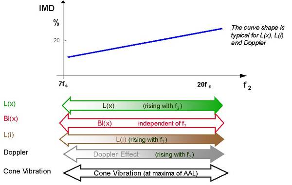
The figure above illustrates the interpretation of the intermodulation distortion measurement using a fixed low frequency tone f1 and a high frequency tone f2 which is varied over the audio band (“voice tone sweep”). While the stiffness nonlinearity can not produce significant intermodulation, the other nonlinearities generate wide-band distortion which can not be detected by a harmonic distortion measurement.
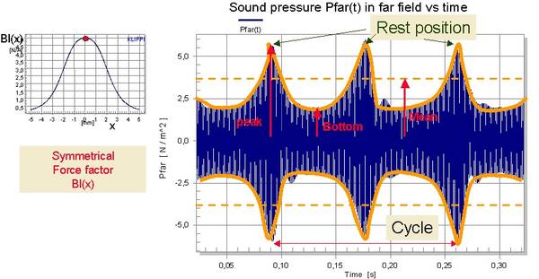
The figure above shows the intermodulation of a high frequency tone f2 by a low frequency tone f1 caused by a nonlinear force factor Bl(x) characteristic. If the voice coil is at the rest position x=0 the instantaneous value of Bl(x=0) is maximal and generates the peak in the envelope of the sound pressure signal. For a negative and positive peak excursion, the Bl-value becomes minimal generating the bottom values of the envelope. The temporal variation of the envelope of the high-frequency generates a fluctuation and roughness in the perceived sound.
There are two factors (at least) making the transition between THD and IMD difficult.
Some mechanisms produce THD and IMD in a certain relationship, for example BL(x), while others (for example Kms(x) produce THD and IMD in a very different relationship. It is easy to lower THD in a driver by having BL(x) and Kms(x) work against each other, but that would only increase IMD.
At the same time, if we look at how THD is interpreted, we do not get factors like power compression as part of this equation at all. A more immediate factor than heat is flux modulation. Playing a transient will produce one result, but playing the same transient twice within a very short amount of time will produce two different results. Such artifacts hardly filters as harmonic distortion, but it sure is a very audible form of intermodulation distortion.
And then we have not even discussed AM vs FM. I mean, FM is arguably less audible than AM, but factors causing FM are commonly not filtered as harmonic distortion.
What size of a compression driver had you in mind (if any)? What lower frequency limit?... a waveguide with a custom phase plug ( maybe as a replacement in an excisting compression driver) which has a great constant directivity behaviour for at least 4 octaves without using diffraction mechanisms where the bias is much more put on sound quality instead of maximum output compared with excisiting solutions ( phase plug much more focussesd on great wavefront coherence than high compression/ cheap to manufacture) ...
I think we are already not that far from your 4 octaves actually.
Last edited:
Right now there is this waveguide being made (422 x 364 mm; 1,4" throat for 18Sound ND3T) -
I'm really eager to see how it turns out, it's probably my best so far. Two different loudspeakers will be made with it, the second one with BMS 4554. Hopefully, we'll see the measured data soon.
I'm really eager to see how it turns out, it's probably my best so far. Two different loudspeakers will be made with it, the second one with BMS 4554. Hopefully, we'll see the measured data soon.
Attachments
...which has a great constant directivity behaviour for at least 4 octaves without using diffraction mechanisms...
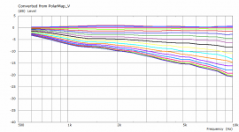
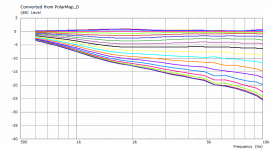
I think the speaker that I built recently comes close. The DI is almost perfectly flat from 1kHz to 16kHz.
On CNC router from a solid block of MDF. As this worked so well for me in the past, no reason to change it. I'd maybe prefer a different material myself but actually these are not for me.How is the waveguide in 2494 made? 3D print or 3D-CNC?
Yeah, I think we should extend the goal at least by an octaveI think the speaker that I built recently comes close. The DI is almost perfectly flat from 1kHz to 16kHz.
")
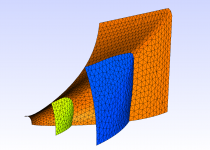
Trying to divide the interior of the horn into several subdomains. If I understand it correctly, this should speed up the calculation considerably, hopefully even make it more stable.
BTW, these surfaces can also be used for the "field" feature, i.e. to show a pressure distribution across of it. These can be placed anywhere you want along the length, can be flat or not (I gathered from ABEC manual that it is better to avoid narrow spaces, i.e. not to join walls at sharp angles).
BTW, these surfaces can also be used for the "field" feature, i.e. to show a pressure distribution across of it. These can be placed anywhere you want along the length, can be flat or not (I gathered from ABEC manual that it is better to avoid narrow spaces, i.e. not to join walls at sharp angles).
Attachments
Last edited:
Right now there is this waveguide being made (422 x 364 mm; 1,4" throat for 18Sound ND3T) -
I'm really eager to see how it turns out, it's probably my best so far. Two different loudspeakers will be made with it, the second one with BMS 4554. Hopefully, we'll see the measured data soon.
Same entrance angle for both drivers?
- Home
- Loudspeakers
- Multi-Way
- Acoustic Horn Design – The Easy Way (Ath4)