Fibonacci was only a suggestion! For large numbers the quotient of two adjacent numbers approaches the golden section ratio 0.618.
You could start with 1 and then for each next number divide the previous by 0.618, so 1, 1.618, 2.618, 4.237, 6.855, ...
is there some obvious mathmatical reason I'm missing as to why this might help?
I read the link you provided as it looks to me that he selected the 26 mm deep waveguide fro the T34 not the deepest OS 43 mm deep version. Did I read wrong ?
No, you got that right.
Somewhere between the lines he states why he opted for the 26 mm WG.
In terms of performance, the differences between the OSWG and the 26 mm are small.
Last edited:
is there some obvious mathmatical reason I'm missing as to why this might help?
I would think that the Fibonacci series is highly uncorrelated, i.e. the numbers bear no relationship to each other. This would be a good thing, but it would also be a very small factor.
In the calculations there will be frequencies where the data is not well resolved and these can/will cause serious singularities in the matrix inversion. A random set of points would likely make this problem less of an issue. But with SVD this is not a real problem and the numerics should find the right answer regardless of the spacing.
I still wait for some parts as I had to change the mounting flange to adapt for a closer position of the first port. It will go a bit slower now, for obvious reasons. I also hoped for a bigger progress with the software but as I have to work at home with two little kids running around, things like these are actually much more difficult now... Stay well!
Last edited:
Hello
I was wondering if an asymmetric horn would serve to correct the position in the room and direct the dispersion to minimize possible bounces with the side walls, I speak from my absolute ignorance.
In this image I have joined two horns with horizontal dispersion of 90º and 60º
or would this asymmetry break all the charm of the horn? Should the driver have a certain angle in the vertical plane pointing to the center of the mouth?
Just some crazy ideas from my confinement ...
Attachments
I was wondering if an asymmetric horn would serve to correct the position in the room and direct the dispersion to minimize possible bounces with the side walls, I speak from my absolute ignorance.
In this image I have joined two horns with horizontal dispersion of 90º and 60º
or would this asymmetry break all the charm of the horn? Should the driver have a certain angle in the vertical plane pointing to the center of the mouth?
Just some crazy ideas from my confinement ...
It is theoretically possible to make a waveguide with virtually any pattern. The question is what pattern do you want? Why?
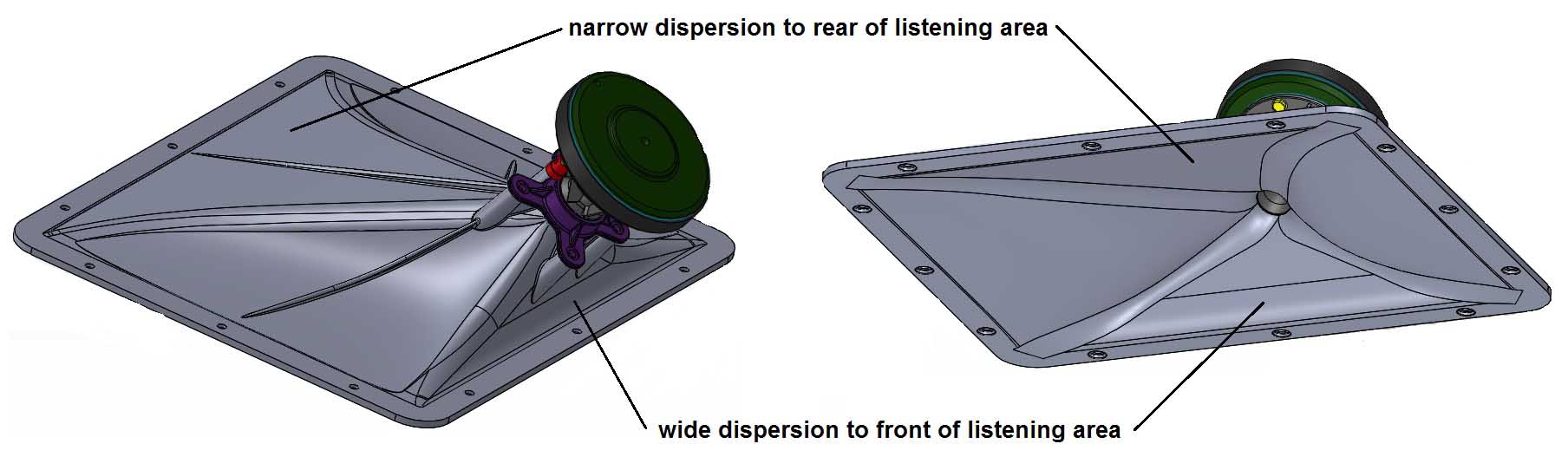
Some horizontal asymmetry could be useful to create a lopsided polar pattern where there is a stronger beam away from center on one side and a lighter one on the other. This pattern lends itself to a configuration that will expand the sweet spot. The problem then become how to match the woofer to this lopsided pattern. Not impossible, but not easy either.
I would, of course, make the device rounder and not square-ish.
The direction that the driver has with the throat will strongly affect the pattern, but, in general, I would not think that it should be pointed at the center of the mouth. That's not what my approach would do.
Thanks for the answers,
very interesting this approach, thanks
In reality, the idea is to direct the two speakers towards a theoretical listening point, without aiming directly at it, as well as reducing reflections with the side walls. My listening room will be L 4.75m x W 3.58m x H 2.6 (15.6ft x 11.7ft d 8.5ft).
Good question that of the woofer, I had not thought about that aspect and although its dispersion is less linear if it is necessary to think about a correction, good challenge.
As for the orientation of the throat towards the center of the mouth, I have mentioned it as a visual example, effectively aiming at the center is not in my imagination either, that would equalize, distort the angles and focus directly on the listening point, but it is the question of whether it should have a slight angle.
I take note of the circular profile.
Thank you
........Some horizontal asymmetry could be useful to create a lopsided polar pattern where there is a stronger beam away from center on one side and a lighter one on the other. This pattern lends itself to a configuration that will expand the sweet spot.....
very interesting this approach, thanks
In reality, the idea is to direct the two speakers towards a theoretical listening point, without aiming directly at it, as well as reducing reflections with the side walls. My listening room will be L 4.75m x W 3.58m x H 2.6 (15.6ft x 11.7ft d 8.5ft).
Good question that of the woofer, I had not thought about that aspect and although its dispersion is less linear if it is necessary to think about a correction, good challenge.
As for the orientation of the throat towards the center of the mouth, I have mentioned it as a visual example, effectively aiming at the center is not in my imagination either, that would equalize, distort the angles and focus directly on the listening point, but it is the question of whether it should have a slight angle.
I take note of the circular profile.
Thank you
it is the question of whether it should have a slight angle.
Thank you
In thinking about this it is clear that the driver must be normal to the throat aperture, otherwise the angles won't match the CD and diffraction/reflection will occur.
This type of asymmetric horn was used on the JBL DD55000 Everest:
1985 DD55000 EVEREST
1985 DD55000 EVEREST
Electro-Voice uses assymetry in the vertical plane for its Vari Intense technology. These 2 way speakers are supposed to be wall mounted against the ceiling. It's different, but nonetheless worth looking into.

Last edited:
..., but it is the question of whether it should have a slight angle.
Horn throat entry angle is independent from wall angles so it can be matched to any shape the horn has, i.e. the driver exit angle could be matched perfectly in any case. The question was whether do it - I have no clue, I'd try to simulate that.In thinking about this it is clear that the driver must be normal to the throat aperture, otherwise the angles won't match the CD and diffraction/reflection will occur.
That's exactly my view. I still don't get why to do it in the first place. Isn't is a lot easier just to turn the whole loudspeaker in the desired direction?It is theoretically possible to make a waveguide with virtually any pattern. The question is what pattern do you want? Why?
Some horizontal asymmetry could be useful to create a lopsided polar pattern where there is a stronger beam away from center on one side and a lighter one on the other. This pattern lends itself to a configuration that will expand the sweet spot. The problem then become how to match the woofer to this lopsided pattern. Not impossible, but not easy either.
In the meantime I tried to simulate various phase plugs down to the diaphragm, just to get some basic feel for it. One thing I started to wonder about - the fact that the diaphragm itself is not perfectly rigid so the phase plug areas closer to the center are driven with a delay compared to the edge (i.e. there is a bending wave traveling accross the diaphragm). Is there a simple way to model this other than a complete FE model of the diaphragm materials? From what I have seen in the literature, most just assume a perfect diaphragm and bother "only" with the modes of the compression cavity with the slots. And that is what I wonder about - does have any sense at all to model phase plugs without this being dealt with? Or am I missing something?
BTW, PWT is on its way now.
BTW, PWT is on its way now.
Last edited:
- I tried to estimate a typical speed of the bending wave from the first break-up modes of real diaphrams and it seems to be only a several times higher than the speed of sound in air, at most. If that was the case I'd guess it would have quite a significant effect.
Last edited:
My understanding of compression driver diaphragms is that they are virtually rigid up to fairly high frequencies. The larger the diaphragm the lower the frequency at which this will occur, hence a small diaphragm is preferential to a larger one up until the smaller one is incapable of meeting the SPL requirements (in home use this is unlikely to ever occur.)
When they do start to break-up, it is the rim that tends to take off. JBL had a paper on this several years (decades?) ago, where they showed how this rim resonance could be used to extend the frequency response upwards a little.
Except in extremely detailed analysis at very high frequencies, assuming rigid is fairly accurate.
For a 1 " driver I would say that this frequency is at about 8-10 kHz. Above this, there will be modes of all kinds in the compression chamber, phase plug, the diaphragm and just about everything else. This will make accurate modeling at these extremes very very difficult.
I am perfectly aware that any initial slope of the contour can be achieved, but a driver is axisymmetric and tilting it will require a different slope for every psi angle around the waveguide. While not impossible to do this would be complicated. I would just design for a constant initial slope equal to the driver and keep the driver normal to the aperture. This is far easier to do.
My understanding of compression driver diaphragms is that they are virtually rigid up to fairly high frequencies. The larger the diaphragm the lower the frequency at which this will occur, hence a small diaphragm is preferential to a larger one up until the smaller one is incapable of meeting the SPL requirements (in home use this is unlikely to ever occur.)
When they do start to break-up, it is the rim that tends to take off. JBL had a paper on this several years (decades?) ago, where they showed how this rim resonance could be used to extend the frequency response upwards a little.
Except in extremely detailed analysis at very high frequencies, assuming rigid is fairly accurate.
For a 1 " driver I would say that this frequency is at about 8-10 kHz. Above this, there will be modes of all kinds in the compression chamber, phase plug, the diaphragm and just about everything else. This will make accurate modeling at these extremes very very difficult.
I am perfectly aware that any initial slope of the contour can be achieved, but a driver is axisymmetric and tilting it will require a different slope for every psi angle around the waveguide. While not impossible to do this would be complicated. I would just design for a constant initial slope equal to the driver and keep the driver normal to the aperture. This is far easier to do.
Dome for dome, a larger diaphragm exhibits more surface area. There are many factors including dome shape, material thickness, and material types to lump them all together and make a conclusion.
A larger diaphragm is driven by a more powerful motor, and can make use of a heavier, more rigid diaphragm, than one driven by a pea-shooter motor.
Domes and ring radiators do not exhibit the same characteristics with regards to break up. Have you seen the BMS ring radiator diaphragms?


Thank you. So below the actual break-up it should be a non issue. That's good.... Except in extremely detailed analysis at very high frequencies, assuming rigid is fairly accurate.
Yes, that's what I meant. If printed or milled with CNC, which is quite common these days, at least in DIY, it really doesn't matter. The initial slope will always be constant around the waveguide (i.e. matching the driver). What will vary is the target wall slope (the coverage angle). With the waveguide formula presented before it's actually plain simple to do - take your throat and mouth curves and join them by the use of the formula around the waveguide. Keep the throat angle constant, calculate the coverage.... a driver is axisymmetric and tilting it will require a different slope for every psi angle around the waveguide. While not impossible to do this would be complicated. I would just design for a constant initial slope equal to the driver and keep the driver normal to the aperture. This is far easier to do.
Last edited:
Comparison of different diaphragm materials, including Klippel scanning of the diaprhagms.
The Use Of Beryllium In Transducers — VUE Audiotechnik
The Use Of Beryllium In Transducers — VUE Audiotechnik
- Home
- Loudspeakers
- Multi-Way
- Acoustic Horn Design – The Easy Way (Ath4)