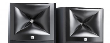
As for horns and their 'signature', I can endorse the reference research by Newell and Holland in this area. Deep horns(ystems) (diaphragm-to-mouth length > 34 cm), with the exception of multicells, were significantly more often identified as "horn" in the study.
In my experience, the narrow, angled (and therefore deeper) Danley horns sound more like typical horn speakers than the Jerichos for example. However, it should be noted that the space itself and the distance to the speakers can also affect perception.
In my experience, the narrow, angled (and therefore deeper) Danley horns sound more like typical horn speakers than the Jerichos for example. However, it should be noted that the space itself and the distance to the speakers can also affect perception.
Last edited:
The more I think about phase plugs the more I realize I probably don't understand even the most basic principles. After reading Dr. Geddes' patent I still wonder what is actually the sufficient and what the necessary part. However I'm lucky enough that I can ask you here.
What I understand:
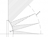
It is desirable to have a uniform volume velocity across the surface "S" (see the drawing attached).
What I don't understand:
Is the volume velocity at the entrance of each particular slot "Si" dependent not only on its (projected) area but also on its actual radial position and the respective positions of the other slots?
BTW, even though it's probably not a good analogy (so regard it as unrelated), this led me to the following thought experiment with which I really can't help myself with. Even my wife is not sure anymore (!). There's a bucket with a moving piston, some liquid inside (maybe clay) and several holes at the bottom. My questions are: 1) will the volume velocity of the outgoing liquid for each of the holes be dependent not only on its area but also on the positions of the other holes, and 2) will the volume velocity be uniform across the area of the center hole?
What I understand:
It is desirable to have a uniform volume velocity across the surface "S" (see the drawing attached).
What I don't understand:
Is the volume velocity at the entrance of each particular slot "Si" dependent not only on its (projected) area but also on its actual radial position and the respective positions of the other slots?
BTW, even though it's probably not a good analogy (so regard it as unrelated), this led me to the following thought experiment with which I really can't help myself with. Even my wife is not sure anymore (!). There's a bucket with a moving piston, some liquid inside (maybe clay) and several holes at the bottom. My questions are: 1) will the volume velocity of the outgoing liquid for each of the holes be dependent not only on its area but also on the positions of the other holes, and 2) will the volume velocity be uniform across the area of the center hole?
Attachments
Last edited:
"Clearly, a horn used for the reproduction of the mid-frequency range in a studio monitoring system should have a diaphragm-to-mouth length of less than 340 mm if the characteristic horn sound is to be avoided"As for horns and their 'signature', I can endorse the reference research by Newell and Holland in this area. ...
This is funny, isn't it
")
What I don't understand:
Is the volume velocity at the entrance of each particular slot "Si" dependent not only on its (projected) area but also on its actual radial position and the respective positions of the other slots?
I think, that all depends on the frequency range in the question. If we considering a frequency range below the first cavity mode, then the radial pressure distribution p(r) in the chamber is constant in every point of the chamber. Then the volume velocity Q can be calculated just as ratio p/Zai, where Zai is acoustic impedance of the i-th slot (rho*c/Sd). However, in a frequency range above the first cavity mode the pressure distribution p(r) is not constant, thus, the volume velocity will be also dependent on the radius. Actually, p(r) is strongly dependent on a shape of the compression chamber (above the first cavity mode). If you want to optimize the driver, i.e. the phase plug, at the higher frequencies, first you need is to find the modes shape function of the chamber. For simple compression chamber shapes it can be done analytically. However, for complex shapes numerical solution is only available. But it is only one part of the problem. Another problem is coupling of acoustical modes of compression chamber with mechanical modes of the diaphragm. Thus, if you want to get best performance of the driver at higher frequencies you should to optimize both shape of compression chamber and shape of the diaphragm. All that was considered by Jack Oclee-Brown in his phd thesis
.
Last edited:
... (rho*c/Sd)...
*here Sd means area of the slot (not diaphragm) !
Thanks Dmitrij, that was the part I wasn't sure about. For one slot only, I could imagine it would work like that, but was not sure of what happens if more slots are added. Good.If we considering a frequency range below the first cavity mode, then the radial pressure distribution p(r) in the chamber is constant in every point of the chamber. Then the volume velocity Q can be calculated just as ratio p/Zai, where Zai is acoustic impedance of the i-th slot (rho*c/Sd). ...
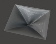
- For convenience, attached is the script file for a "JBL like" waveguide for the version 4.5.
There are maybe fifteen parameters affecting the shape - mix them as you wish (I didn't run BEM for this one).
I'd say that this particular piece makes a nice overview of possibilities of the tool as almost all the basic features are there. The exact opposite would be an OS waveguide.
There are maybe fifteen parameters affecting the shape - mix them as you wish (I didn't run BEM for this one).
I'd say that this particular piece makes a nice overview of possibilities of the tool as almost all the basic features are there. The exact opposite would be an OS waveguide.
Attachments
Last edited:
In fact, based on the simulations (presented before), it appears that actually quite good results regarding the radiation pattern could be achieved by using just the dome/cap connected directly to a conical waveguide, i.e. without any phase plug. But of course you loose efficiency that way, there's no compression. Excursion would be higher and I'm not sure a common compression driver could hande that without excesive distortion. The frequency response alone could be smoother than with a phase plug though.Makes sense to me a circular cap in the throat of a horn has a wider dispersion than a piston.
Last edited:
- For convenience, attached is the script file for a "JBL like" waveguide for the version 4.5.
I'd say that this particular piece makes a nice overview of possibilities of the tool as almost all the basic features are there. The exact opposite would be an OS waveguide.
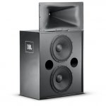
Your JBL (M2?) WG clone is similar to the original, however, there are some subtle but essential differences in the throat area.
The vertical trenches in the original are more pronounced and rather sharp edged.
The horizontal "knuckles" are partly covering the entrance.
The M2 WG is clearly a modern variation on the classic diffraction slot.
Attachments
Last edited:
The more I think about phase plugs the more I realize I probably don't understand even the most basic principles. After reading Dr. Geddes' patent I still wonder what is actually the sufficient and what the necessary part. However I'm lucky enough that I can ask you here.
What I understand:
It is desirable to have a uniform volume velocity across the surface "S" (see the drawing attached).
What I don't understand:
Is the volume velocity at the entrance of each particular slot "Si" dependent not only on its (projected) area but also on its actual radial position and the respective positions of the other slots?
BTW, even though it's probably not a good analogy (so regard it as unrelated), this led me to the following thought experiment with which I really can't help myself with. Even my wife is not sure anymore (!). There's a bucket with a moving piston, some liquid inside (maybe clay) and several holes at the bottom. My questions are: 1) will the volume velocity of the outgoing liquid for each of the holes be dependent not only on its area but also on the positions of the other holes, and 2) will the volume velocity be uniform across the area of the center hole?
As someone else pointed out, as long as the wavelengths are longer than the dimensions there will be a constant force/ pressure at each opening. But our situation is even simpler.
That's because our chamber is very very wide and very very short. This means that only radial resonance are an issue. This is precisely what Smith studied way back when. He analyzed the possible resonances across the chamber by assuming a flat space. Then he found the best places for the channels to avoid these modes.
The problem is that these modes need to be excited to be of concern, and they are not excited by a uniform piston to any great extent, so they aren't an issue - as long as the diaphragm has a uniform vibration. But when it doesn't, then this aspect makes the acoustic resonances irrelevant because the mechanical ones will dominate (except in the rare instance when the modes match, which is almost impossible.) IMO this makes Smith's approach not very useful. And, in fact, his own data are not at all conclusive that his approach was any advantage at all.
What I proposed to do was to have a phase plug that would allow me to control the volume velocity (VV) contour at the phase plugs exit. This is because it is know (it's in my book so at least I know it) that one does not want to excite an OS waveguide with a perfectly flat wavefront, but instead one that has a gradual change in VV. This will suppress the first HOM if done correctly. The second HOM can also be suppressed but with a much more elaborate calculation.
So in my mind it is the ability to control the phase plug exits VV contour that is desired and not the approach of Smith, which has not been shown to be effective.
Just for clarity which were the statements you thought were inaccurate? Tom's comments have been quoted a few times so it would be useful to know.
I'm not going to critique the entire text but this line is clearly wrong
mouth diffraction is an issue with horns, not popular but for any given shape, the larger you make it, the less of a problem it is because the SPL is always falling as you move from the origin.
The pressure declines as the wave moves out, but the circumference also increases at the same rate - half the pressure over twice the length, etc. This will yield the exact same level of mouth diffraction in the far field no matter what distance along the device the mouth is at. Only a mouth flare will reduce this diffraction, again no matter how long the device is.
That's just the one that jumped out to me at first.
Thank you very much for your elaborate answer. I'm really getting some grasp for it now, I think.
Anyway, I found a video of a presentation made by Jack Oclee-Brown, speaking about this very issue: YouTube
He seems to be saying, as I undertand it, that it is actually the presence of the phase plug channels (the velocities leaving the chamber, as he says) that will excite the modes in the chamber (time 22:40). Now, to be honest, from this I'm a bit confused again - will the modes get excited by this even if the diaphragm is perfect? You seem to say that they won't.
Last edited:
"Clearly, a horn used for the reproduction of the mid-frequency range in a studio monitoring system should have a diaphragm-to-mouth length of less than 340 mm if the characteristic horn sound is to be avoided"
This is funny, isn't it
It's kinda funny indeed, considering that nearly all (PA) manufacturers have adhered to this 'convention' since Holland and Newell revealed their research.
Here's their related Article: "Round the Horn" published in Studio Sound (March, 1994).
Attachments
He seems to be saying, as I undertand it, that it is actually the presence of the phase plug channels (the velocities leaving the chamber, as he says) that will excite the modes in the chamber (time 22:40). Now, to be honest, from this I'm a bit confused again - will the modes get excited by this even if the diaphragm is perfect? You seem to say that they won't.
I would say that there is a possibility of some small excitation, but again, Smith does not show anything conclusive. I don't know (and I am not going to research it,) what evidence he has to support his contention. Did he do a simulation showing these standing waves being generated by a ridgid piston? I'd like to see that if he did.
But still, the mechanical modes will dominate once the diaphragm begins to break up. But there could be a region where the radial modes lie below the diaphragm modes where this channel excitation could be significant (and I use that word cautiously because I just don't think that this would be significant, but what does "significant" mean anyways?)
Last edited:
It's kinda funny indeed, considering that nearly all (PA) manufacturers have adhered to this 'convention' since Holland and Newell revealed their research.
That doesn't make it correct.
And anyways that paper is so out-of-date that it is not of much relevance when one now has waveguide with virtually no resonances. It is very misleading to quote analysis of devices that we know are bad, and why, in a thread where we have devices that don't have any of those problems. Let's move on from where we are now, not where we were decades ago.
Last edited:
Yeah he did, I believe. It should be in his PhD thesis. My take away from that was that it is actually the diaphragm that will spoil the effort in the end. So without taking extreme measures to make it all balanced (which was what they apparently tried with the Axi2050 driver at Celestion), there's really no point.... Did he do a simulation showing these standing waves being generated by a ridgid piston? I'd like to see that if he did.
Last edited:
There are so many things going on above about 8k for mid sized CDs, and say 10k for the smaller drivers like I use, that it is such that one needs to actually build and test the results. Sims can help of course, but something is always left out. In the end I don't worry too much about these very high frequency aberrations. I know they are there and my suggestion is to use the smallest driver that you can get away with as this will always push these problems higher and hence less problematic.
Anyway, I found a video of a presentation made by Jack Oclee-Brown, speaking about this very issue: YouTube
Thanks, I have missed that presentation !

- Home
- Loudspeakers
- Multi-Way
- Acoustic Horn Design – The Easy Way (Ath4)