Couldn't a thin layer of a soft fabric (maybe wool) placed between the diaphragm and the phase plug, basically dampening the compression chamber, be beneficial? I understand that the acoustic velocities are small there but nevertheless.
BTW, what are the common distances between diaphragms and the plugs?
BTW, what are the common distances between diaphragms and the plugs?
Last edited:
As for the "Phase Plug Transient Smear" as described by Gunness in the referenced paper - how important it really is? This would also speak for drivers with smaller diaphragms I suppose. This is one of the many things I have never thought about.
If I could offer an opinion then, to me, what Dave showed was paramount to what I have been saying all along - that you have to get rid of these reflections and diffractions which are all time delay effects (hence visible in that domain.) His use of DSP was insightful, although, in the end, not very practical at that time, certainly are today of course. But the take away point for this thread is that these waveguides won't have the problems that Dave showed. It is always much more effective to get rid of the problems at the source than try and cure them after the fact.
Couldn't a thin layer of a soft fabric (maybe wool) placed between the diaphragm and the phase plug, basically dampening the compression chamber, be beneficial? I understand that the acoustic velocities are small there but nevertheless.
In many ways my foam plugs will do a reasonable amount of that, and more.
Last edited:
It seems to me that what he is referring to actually should be an inherent property of phase plugs in general, even before sound enters the waveguide:... But the take away point for this thread is that these waveguides won't have the problems that Dave showed. It is always much more effective to get rid of the problems at the source than try and cure them after the fact.
"The openings in a phase plug are arranged in such a way that, from any point on the diaphragm, the path to an opening is relatively short. The designer of the compression driver intends for all of the sound power produced within the driver to leave via the “nearest exit”. However, a significant fraction of the sound energy arriving at a phase plug opening will either continue past it or reflect back from it; in either case arriving later at other phase plug slots where the sound is divided again, ad infinitum. Rather than a single acoustical impulse, the response exhibits a decaying sequence of impulses."
Last edited:
The volume of the throat chamber formed by the distance between diaphragm and phase plug creates an acoustical band pass, cutting off HF response. You can model VTC in Hornresp and see the effect.Couldn't a thin layer of a soft fabric (maybe wool) placed between the diaphragm and the phase plug, basically dampening the compression chamber, be beneficial? I understand that the acoustic velocities are small there but nevertheless.
BTW, what are the common distances between diaphragms and the plugs?
For output to 16-20kHz, the distance between diaphragm and phase plug is held to under 1mm, regardless of diaphragm diameter or composition.
The slits in the phase plug are optimally twice that distance, <2mm.
Art
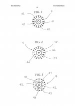
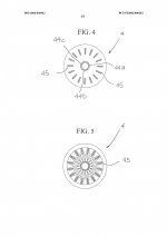
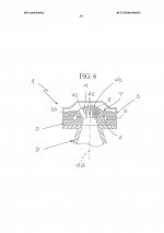
18Sound's 3P Patent.
"The Proprietary Phase Plug (3P) technology identifies a combination of radial and
tangerine slot geometric design. With its short openings and high flare rate value, 3P
technology assures low distortion in the mid-high frequency range, providing a smooth
coherent wavefront at the horn entrance."
"The Proprietary Phase Plug (3P) technology identifies a combination of radial and
tangerine slot geometric design. With its short openings and high flare rate value, 3P
technology assures low distortion in the mid-high frequency range, providing a smooth
coherent wavefront at the horn entrance."
Attachments
-
 AFKJgEQMEz5z8PFmYTaqXVxSX5RQ6n2PvP-q8e4Hu_5kuK0KHIJQq-VBw1RvS5Jbjaf_55dh-N-vxexqsZ3JyrqEKmLCfkck.jpg191.4 KB · Views: 363
 -
 6BpTKpgZAtXtSCKCbtOJuWMiXLcsOKclS_eDuaAfBJ6YRYQ8vnAihI2kP2bRYLu1NeC8mIsNvKkWI-LWX5pwvez-s61M_AP4.jpg205.5 KB · Views: 343
 -
 7ciKDwCsnkR0pN3K4G4Soe2e97LBssaJC1eLhXruoD2EpnFB2pUN2LyIJCoD-giuxcUbsRUjmAENzZbh06QqbeHp3-V87fdA.jpg198.4 KB · Views: 346
 -
WO2004040942 - EQUALISER, OR PHASE PLUG, FOR ELECTRO-ACOUSTIC TRANSDUCERS.pdf582.4 KB · Views: 82
Last edited:
That might be a very different case as they probably aimed at a flat wavefront at the exit of the driver. What is required here, at least as I understand it, is to keep the waves diverging to sum smoothly into one spherical wavefront with required radius at the exits of the slots.In order to improve HF response BMS incorporated a PARABOLICphase plug design in their HE coaxial compression drivers.
Consider path lengths here, and wavelengths. These effects effects are fairly high up and in much study by the CD manufacturers have either resolved or concluded that they don't need any resolution. The proper phase plug design is pertinent but zagaja sent me a modified design to test with what seemed should work better, but it was not so different actually.
what Art says is true, it is an acoustical BP filter, where we operate on the LP side. That's why the power response falls for a Constant Directivity waveguide. That's also why you always see two bumps on the impedance curve - the null is this resonance.
what Art says is true, it is an acoustical BP filter, where we operate on the LP side. That's why the power response falls for a Constant Directivity waveguide. That's also why you always see two bumps on the impedance curve - the null is this resonance.
Last edited:
That might be a very different case as they probably aimed at a flat wavefront at the exit of the driver. What is required here, at least as I understand it, is to keep the waves diverging to sum smoothly into one spherical wavefront with required radius at the exits of the slots.
No, I dont think so, they sell other drivers specifically designed for Line Arrays > flat wavefront.
I referred to Tom Danley, because his horns require a diverging (spherical wavefront) to perform at their best.
From Patrick's thread, as well as this forum (Where's our virtual psycho, when you need him?):
"For one, little (good) has been said here about the conical horn, yet, its walls have the least change (none) one can have, it is a segment of spherical radiation space bounded by a physical boundaries and if driven at an acoustically small point, radiates a section of spherical wave front, with the effectively the same arc, regardless of frequency, down to where its mouth size losses control.
The nonlinear (shocking up) distortion in air is also less in a conical horn as its initial expansion is very rapid. This problem is sort of a “wavelengths traveled times the SPL” issue so a Hyperbolic would be worse than exponential of the same mouth and low cutoff etc.
Not all compression drivers are created equal or create the same problems.
For example, in subjective listening, on two identical 50 degree conical horns, both made “flat”, both having similar responses and acoustic phase, still sounded very different.
Of two of the best modern compression drivers available, The B&C DE250 sounded very much like a horn compared next to the BMS 4550 which sounded very “open” and airy.
The possibly interesting part was the BMS driver has a different internal approach, which so far as the horn is concerned, starts as an acoustically small conical horn inside the driver. There are no phase plug summation slots, (which by path length, generally would appear to produce a converging, not diverging wave front one would want in a source that was large enough to already exhibiting some directivity at the throat).
As a result, with an acoustically small origin and small acoustic size where the break point in angles was, there was much less “origin” garbage from the BMS style phase plug arrangement which produces a diverging wave front from inside the driver.
Yes, mouth diffraction is an issue with horns, not popular but for any given shape, the larger you make it, the less of a problem it is because the SPL is always falling as you move from the origin.
One practical down side of conical or other constant directivity devices is that they reveal the drivers true power response which makes hifi folks uneasy, a truth they don’t want to see or have to deal with as “things are suppose to be flat”.
A related down side is that the conical horn (for a given size) exhibits somewhat less low frequency loading on the driver due to its rapid initial expansion also.
There are solutions to most things, practical or not is another issue.
I have been working with a company on a new phase plug geometry for dome compression drivers, so far, that seems to work too.
Best,
Tom Danley"
And:
"The BMS 4550 is a non-dome driver and has a couple nice things going for it.
For one, the impedance peaks at the low end of it’s response are lower than most 1 inch drivers and this makes the high pass crossover easier if passive (like many of ours are).
Second though is something which may or may not be important depending how it’s used. Sound travels at the speed of sound of course and so if one examines the relationship of the radiator, phase plug and exit, one finds that these relationships can vary quite a bit.
That matters because except near breakup, the dome acts like a piston and so when you trace the path lengths from the dome through the phase plug, one finds that some drivers would produce a converging wave front at the exit, while others a plane wave and a few a diverging wave front.
With our horns, the goal is to make them act like they were a single point source driver and so at 20KHz where the exit would be having an effect on the pattern, that is reduced / eliminated by having a source that already has curvature to it.
That is partly why I use conical horns too, the sound does not have to change or refract like can happen if the horn wall angles changes too much / quickly before the pattern is established.
A simple conical horn driven by a point source (a source that is too small to have directivity) radiates a simple portion of a sphere.
That way, the entire angular distribution is more even, has no hf character or an interference pattern when you walk past it playing pink noise. A source that produces an interference pattern will have an audible to very audible combing with pink noise when you walk the pattern."
Last edited:
You don't agree?
Let me add my 2 nano cents:
This:
"The B&C DE250 sounded very much like a horn compared next to the BMS 4550 which sounded very “open” and airy"
is what I have experienced in real life, with several BMS drivers versus "traditional" dome compression drivers, all mounted in original Danley products.
FWIW of course
Last edited:
I didn't ask you to comment, I just wondered about the implication of your reply.
Danley's quotes may not be scientific, but nevertheless contain useful information from a very experienced engineer.
After all, we must measure in practice, but also experience how our theoretical models work out.
Danley's quotes may not be scientific, but nevertheless contain useful information from a very experienced engineer.
After all, we must measure in practice, but also experience how our theoretical models work out.
Last edited:
Just for clarity which were the statements you thought were inaccurate? Tom's comments have been quoted a few times so it would be useful to know.The parts that were not subjective opinion are somewhat inaccurate.
- Home
- Loudspeakers
- Multi-Way
- Acoustic Horn Design – The Easy Way (Ath4)