Hi TrevorF,
Kindest regards,
M
I am aware of a jig to cut an ellipse from a flat material, but I cannot fathom how to apply it to 3D.It's a bit like a circle cutting jig for a router but you have a second pivot pin.
Kindest regards,
M
I was planning to rotate the router 90 deg so it's pointing out at the tip of the arm and then put the jig on an angle that would be equal to the waveguide angle. If the mold is on a lazy susan with the mouth at the base and the throat at the top, the jig would be placed at the height of the throat and the radius of waveguide apex. The arm of the jig would be horizontal at throat and at its minimum radius. Sorry if that was kind of rambling, I couldn't think of an easy way to draw a picture given all the weird angles involved. I'm still trying to figure out a simple way to motorize the lazy susan to make the whole process a little less labor intensive
Hi TrevorF,
thank you for the reply.
Then you say:
The mechanical implementation may be tricky.
Kindest regards,
M
thank you for the reply.
No, no rambling at all; I have the false impression that I understand it. That is very clever.Sorry if that was kind of rambling, I couldn't think of an easy way to draw a picture given all the weird angles involved.
Then you say:
parallel with one of the arm defining the semi-minor axis.pointing out at the tip of the arm
The mechanical implementation may be tricky.
Kindest regards,
M
Considering the current status of ATH have you had any thoughts about open sourcing the project? I see back in 2020 you made some posts in this thread here and here but at the time wanted to keep it closed. Moving it over to github with an appropriate license would allow you to retain control and stay credited for your work while allowing public contributions. It would also allow repackaging with Gmsh and maybe also gnuplot which could really streamline setup and use. I can also very much see the appeal in a GUI to coordinate horn script generation, 3d viewer, automatic ABEK evaluation and viewing/comparison of plots and possibly also optimisation tools. For optimisation in particular i've been researching Dakota which has a whole range of tools and techniques for automated script reading/modifIcation/analysis of results and even has a standalone c++ package that can be integrated directly into an existing source. ATH is already fantastic and i very much believe it would have ongoing community support and contributions.- Sorry about the end of Ath development/availability, it's just a very long way from writing some code for myself to making it available and usable to public (all the documentation, etc.). For a year or so it was already a mess and it became so little rewarding for me that I just decided it's time to stop.
This would be the formula for the generalized OS, i.e. the inverse function to (3) from the OSSE paper (for y from <r0, R>):the profile can be as easily expressed as a function x( y ), i.e. inverted.
Last edited:
I don't feel it the same way but I encourage anyone to feel free to start from scratch[...] and i very much believe it would have ongoing community support and contributions.
")
Ath is nothing more than a .geo file generator now. I've already shared all the important stuff and I would be ashamed to publish my spaghetti code. Adding GUI, perhaps connecting it to some open-source BEM solver, optimization, etc., it's basically starting from scratch. The profile formulas are public domain now I guess, so there's no limit to their use.
Last edited:
Thanks for the tip, those look pretty good. I already bought them and am working on a horn -Got my eye on a bigger coaxial if I ever get a bigger printer and that’s the Redcatt 6” https://redcatt.de/REDCATT-CX601X8 [...]
The phase plug terminates at roughly 19mm diameter, which is nice. Then a duct of several cm will have to follow...
Yes!!! I love it when other people try the thing I want to do but don’t have time or means to pull it off.
Did I show this independent test of the unit?
Works reasonably good on Google translate to English.
https://hifi-selbstbau.de/index.php/hsb-datenblaetter/koaxialchassis/redcatt-cx6f140fx8
Did I show this independent test of the unit?
Works reasonably good on Google translate to English.
https://hifi-selbstbau.de/index.php/hsb-datenblaetter/koaxialchassis/redcatt-cx6f140fx8
It’s quite clear that diy speakers in Germany is a widespread hobby.
This is the tweeter on the coaxial mabat is working with: https://audioxpress.com/article/test-bench-the-140fcd-1-compression-driver-from-redcatt
I asked the distributor of redcatt in Europe/Germany and the bigger coaxial with attached center horn is easy to remove if one like to fiddle with those.
Next one up on my bucket list would be Oberton 8” https://www.oberton.com/en/products/neodymium-coaxials/465-8nmb250vcx.html?showall=1
https://www.oberton.com/images/news/ND45_in_Voice_coil_Magazine.pdf
And for a high output one: https://www.oberton.com/en/products/neodymium-coaxials/467-10ncx.html?showall=1
It got the fancy new composite diaphragm..
And for some design inspiration https://www.aforara.com/collection
There is never a distance in any room where this is true. There is always a direct wave and a reverberant field, distance does not meld things together. The room and distance can have a significant effect on the timing of the direct/reverb, but no location has only reverb, there is always a direct signal which can be audibly filtered out in better and worse ways depending on the VER.If one always listens further away where its only roomy sound
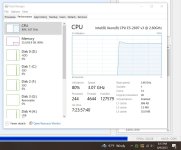
Now that CPU are reliably exceeding ten cores, I noticed something interesting with ABEC. It seems to tap out at 20 cores.
So it might be worthwhile to turn off hyperthreading on your Intel CPUs if you're doing ABEC sims.
I'm using a Xeon E5-2697 (14 cores) that I paid a whopping $39 for, and ABEC refuses to use more than ten hyperthreaded cores out of 14. (It shows up as "20" in the attached pic because hyperthreading.)
Attachments
Hi, yeah sorry I noticed too late that the text was not accurate enough. I got your remark regarding about same thing earlier already, thanks straightening it up again.There is never a distance in any room where this is true. There is always a direct wave and a reverberant field, distance does not meld things together. The room and distance can have a significant effect on the timing of the direct/reverb, but no location has only reverb, there is always a direct signal which can be audibly filtered out in better and worse ways depending on the VER.
What I ment is perception of mine, sound coming from speakers direction is just different listening further away. I have simplified sound that localizes to direction where the speakers are, frontal sound, as direct sound. Being a hobbyist I'm not too familiar with exact meaning of words, mistake there. Now being corrected few times it should stick.
Further away I cannot perceive direct sound and room sound separately with my setup, they seem to be merged into one roomy sound coming from direction of speakers. There doesn't seem to be distinct room or direct sound, it's just one hazy blob of sound localizing somewhere direction of the speakers. Listening close enough sound seems to clear up, for some reason, localizes much more accurately and timbre changes some. Moving between the two distances, it appears as if influence of local room disappears when close enough.
Comparing the two listening distances perceptually, frontal sound appears to be either very roomy or opposite, rather direct. So, it's just uneducated trying to describe what's hard to describe
Last edited:
Have you tried to increase the Abec process priority? I have a program at work that never throttle up to its true potential until its priority is raised. The same application on a older processor always punish each and every core.Now that CPU are reliably exceeding ten cores, I noticed something interesting with ABEC. It seems to tap out at 20 cores.
So it might be worthwhile to turn off hyperthreading on your Intel CPUs if you're doing ABEC sims.
I'm using a Xeon E5-2697 (14 cores) that I paid a whopping $39 for, and ABEC refuses to use more than ten hyperthreaded cores out of 14. (It shows up as "20" in the attached pic because hyperthreading.)
1. Right-click on taskbar and select Start Task Manager.
2. Go to the Processes tab.
3. Right-click on the process you want then select Set Priority then switch it to what you want.
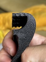
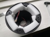
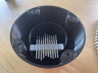
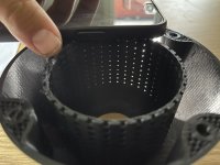
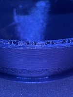
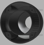
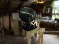
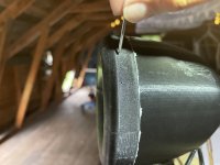
I’m not going to distract to much, but I’m continuing the work on making my tiny 4” coaxial with controlled directivity.
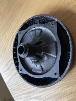
I have since the last time tried adding a center tube in the back chamber that is a press fit against the magnet with micro perforation like example C in this paper. https://mdpi-res.com/d_attachment/a.../acoustics-03-00031-v2.pdf?version=1625566551
So there’s three rows with 36 0,9mm holes close to the open back, then there’s 3x36 0,7mm, 3x36 0,5mm, 3x36 0,3mm.
The tiny holes is one layer thick on my 0,4mm nozzle. In the cad-model I made it 0,4mm.
So the idea was that before the sound can exit the back it needs to squeeze thru these holes first that ads quite a resistance.
Edit: ( didn’t think it through enough and the magnet actually blocks the 0,3mm holes and maybe some 0,5mm ones)
And to be honest I did this test because I was curious if I could print the mpp (micro perforated panel). And if it works it could be a more controlled way of adding flow resistance than fibers or foam. I checked the hole sizes with tiny drill bits. And it’s close but not perfect.
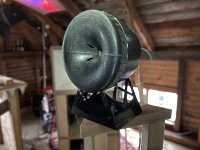
And because I believe that the actual distance to the opening in the back is too long for the range I’m trying to control ~500-2500Hz and the holes alone was not enough of a low pass.
I’m testing melamine foam to increase the low pass, and also I’m making a new waveguide with 3x36 0,5mm holes closer to the waveguide.
I have since the last time tried adding a center tube in the back chamber that is a press fit against the magnet with micro perforation like example C in this paper. https://mdpi-res.com/d_attachment/a.../acoustics-03-00031-v2.pdf?version=1625566551
So there’s three rows with 36 0,9mm holes close to the open back, then there’s 3x36 0,7mm, 3x36 0,5mm, 3x36 0,3mm.
The tiny holes is one layer thick on my 0,4mm nozzle. In the cad-model I made it 0,4mm.
So the idea was that before the sound can exit the back it needs to squeeze thru these holes first that ads quite a resistance.
Edit: ( didn’t think it through enough and the magnet actually blocks the 0,3mm holes and maybe some 0,5mm ones)
And to be honest I did this test because I was curious if I could print the mpp (micro perforated panel). And if it works it could be a more controlled way of adding flow resistance than fibers or foam. I checked the hole sizes with tiny drill bits. And it’s close but not perfect.
And because I believe that the actual distance to the opening in the back is too long for the range I’m trying to control ~500-2500Hz and the holes alone was not enough of a low pass.
I’m testing melamine foam to increase the low pass, and also I’m making a new waveguide with 3x36 0,5mm holes closer to the waveguide.
Attachments
-
 IMG_2292.jpeg380.6 KB · Views: 85
 -
 IMG_2291.jpeg324.3 KB · Views: 89
 -
 IMG_2290.jpeg410.6 KB · Views: 84
 -
 IMG_2285.jpeg256.3 KB · Views: 88
 -
 IMG_2257.jpeg349.2 KB · Views: 101
 -
 IMG_2237.jpeg302.5 KB · Views: 87
 -
 IMG_2220.jpeg289.6 KB · Views: 82
 -
 IMG_2219.jpeg266.4 KB · Views: 81
 -
 IMG_2218.jpeg340.7 KB · Views: 87
 -
 IMG_2221.jpeg83 KB · Views: 85
Last edited:
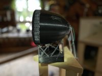
To late to Edit but I did a test where I loosened the screws so that there was a small gap between the waveguide and back chamber and this showed some potential and that’s why I’m trying the perforated side of the waveguide.
I wonder where that idea came from?
I wonder where that idea came from?
Attachments
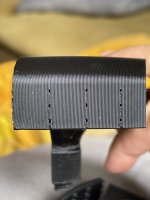
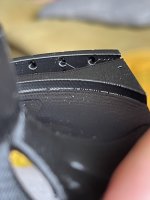
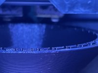
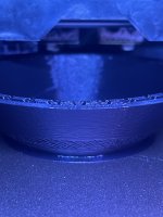
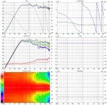
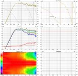
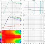
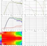
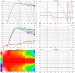
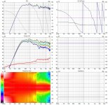
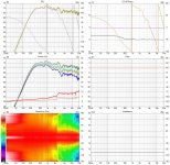
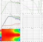
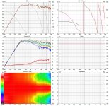
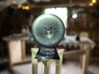
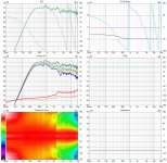
I made a test with perforating the side of the waveguide and studied the effect of enlarging the holes that bleeds the sound from the backside of the cone.
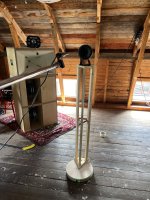
972 enlargements were made and a 10 degree per step spinorama was made each time I enlarged the holes. The speaker never left the speaker stand so the result could be compared.
I thought I was done, I thought that the last one was worse than the one before but I was wrong.
I still don’t know the perfect hole size..
The spinoramas is first the holes taped over. Then the drills that was used was
0,5mm 0,7mm 0,8mm 0,9mm 1,0mm 1,2mm 1,5mm 1,8mm 2,3mm
Attachments
-
 IMG_2311.jpeg268.2 KB · Views: 119
 -
 IMG_2312.jpeg265.5 KB · Views: 102
 -
 IMG_2313.jpeg267.1 KB · Views: 99
 -
 IMG_2314.jpeg264.9 KB · Views: 91
 -
 IMG_2315.jpeg269.5 KB · Views: 97
 -
 IMG_2316.jpeg265.5 KB · Views: 89
 -
 IMG_2317.jpeg268.8 KB · Views: 89
 -
 IMG_2318.jpeg265.7 KB · Views: 94
 -
 IMG_2310.jpeg267.2 KB · Views: 86
 -
 IMG_2309.jpeg268.3 KB · Views: 102
 -
 IMG_2291.jpeg324.3 KB · Views: 110
 -
 IMG_2305.jpeg450 KB · Views: 138
 -
 IMG_2304.jpeg274.6 KB · Views: 131
 -
 IMG_2302.jpeg277.3 KB · Views: 135
 -
 IMG_2303.jpeg300.2 KB · Views: 121
 -
 IMG_2301.jpeg388.3 KB · Views: 121
 -
 IMG_2298.jpeg291.9 KB · Views: 127
 -
 IMG_2297.jpeg747.5 KB · Views: 127
 -
 IMG_2290.jpeg410.6 KB · Views: 126
 -
 IMG_2319.jpeg267 KB · Views: 131
That is a much better idea than a rectangular waveguide - with only two more sides! I never understood the desire for a rectangle.I'm slowly progressing with the ATHEX 460-36...
Compared to assembling a round one, this was a piece of cake.
View attachment 1202307
I would be concerned that the tape is not a rigid surface and to suggest that it's more the distance from the CD diaphragm that is a majority factor. If that's the case then a more random distance would be what I would try. But I don't like using tape as any flexure of the walls will diffract.I made a test with perforating the side of the waveguide and studied the effect of enlarging the holes that bleeds the sound from the backside of the cone.
- Home
- Loudspeakers
- Multi-Way
- Acoustic Horn Design – The Easy Way (Ath4)