Awesome. That would make it perfect.
I confirm now that thicken issue, it is caused by the throat profile as the the profile starts to intersect on itself. Work around is to do it in smaller segments and use loft / patch to fix the outside edge as needed. Many ways are now available when we can work with few surfaces rather than mesh. Surfaces can be then later combined to single body.
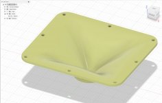
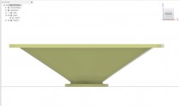
Outside is lofted from bottom ring to top and is thus straight line giving variable thicknes to walls.
I confirm now that thicken issue, it is caused by the throat profile as the the profile starts to intersect on itself. Work around is to do it in smaller segments and use loft / patch to fix the outside edge as needed. Many ways are now available when we can work with few surfaces rather than mesh. Surfaces can be then later combined to single body.
Outside is lofted from bottom ring to top and is thus straight line giving variable thicknes to walls.
Attachments
Last edited:
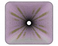
In the meantime, attached is a (relatively) high resolution STL file for the same shape. You can try to compare the two surfaces.
This is the definition file:
ThroatDiameter = 33 ; [mm]
ThroatAngle = 0 ; [deg]
Coverage_Horizontal = 110; [deg]
Depth = 120 ; [mm]
SE_s = 0.7
SE_n = 4.0
SE_q = 0.995
Depth.ConicSectionPart = 1.0
Shape = raw2rect
Shape.FixedPart = 0.01
Shape.CornerRadius = 40 ; [mm]
Shape.StretchExp = 3
ShapeCurve = SF
SF = 1.65,2.3,4,2,5.1,2.9
SF.Rot = 0
Mesh.AngularSegments = 200
Mesh.DepthSegments = 50
Mesh.CornerSegments = 8
Out.DestDir = "D:\Horns"
Out.Write_STL = yes
Out.Write_MSH = no
Out.Write_ABECProject = no
Attachments
Last edited:
I could help you to write some documentation if that would save you some time, if you were willing to release the tools before you write it yourselfI will release it soon. This file will be simply among the output files the tool creates (i.e. the coordiantes of surface points in text format). I have it ready, just have to write some documentation...
")
Thanks but there are completely new things to describe.
- I have just implemented the loft feature into the Add-In so now it takes just one click of selecting the exported text file to get a smooth surface into Fusion 360. Cool.
- I have just implemented the loft feature into the Add-In so now it takes just one click of selecting the exported text file to get a smooth surface into Fusion 360. Cool.
Attachments
Thanks but there are completely new things to describe.
- I have just implemented the loft feature into the Add-In so now it takes just one click of selecting the exported text file to get a smooth surface into Fusion 360. Cool.
Can you add the flanges and bolt holes too so i don't need to do anything?
Great work Mabat! Thank you.
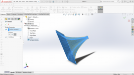
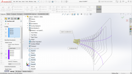
That looks like you have imported the mesh as a surface in solidworks, you have to join all the faces together to get it to thicken. If you merge all those faces together then it changes the geometry. By lofting the splines as shown before you get a single face that can be thickened.Solidworks doesn't want to thicken.
The closest I got with solidworks and a mesh was to get solidworks to slice through the mesh at 5mm increments which gave the same sort of curves as mabat can generate, the problem was they were mesh sketches with a large number of points and it became too unwieldy to use.
The test file mabat posted can be downloaded as igs which should allow you to test it in solidworks.
That's good news, lofting the splines was simple but tediousThanks but there are completely new things to describe.
- I have just implemented the loft feature into the Add-In so now it takes just one click of selecting the exported text file to get a smooth surface into Fusion 360. Cool.
That looks like you have imported the mesh as a surface in solidworks, you have to join all the faces together to get it to thicken. If you merge all those faces together then it changes the geometry. By lofting the splines as shown before you get a single face that can be thickened.
Im could thicken by ticking option in STL import but then when I extrude driver mouting I can't do up to body or surface (thickened mesh).
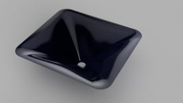
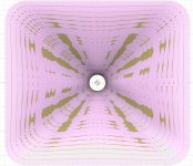
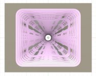
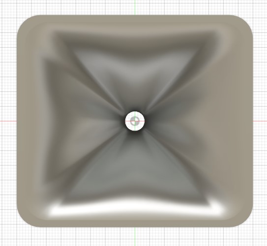
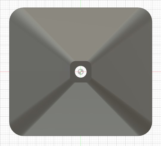
Superimposing the body created with loft with the stl there are no major differences, the spline model is "softer" than the stl due to its triangulation nature. Also when we export it to stl for printing that triangulation will occur again, it will depend on the export parameters to create a surface faithful to the body.
Attachments
Thanks! That looks quite good to me.
The surafce loft is very close to the mesh I turned off the hidden edges to show it more clearly. Mesh surface is pink.
Patching the surface to make a solid and cutting it out of a bigger block to represent a baffle gives exactly the same result. So it's only when you thicken that care needs to be taken to make sure the profile matches.
Attachments
Try lofting without the guide curves, just the profiles, that's how it works in Fusion. Solidworks drives me mad because I don't know enough to make it do what I want, Fusion is much more intuitive, and free for non commercial use.Solidworks is so limited - even intersected profiles don't help.
Here's another way (not necessarily better) to make a solid waveguide with greater thickness without using the thicken command. Looks like this, pdf guide of the steps attached below
Attachments
Ath 4.4.3 beta
For those impatient, here is a beta version with some quick instructions of how to proceed (see the README file): Ath 4.4.3 beta
It should work. What's still missing is the second surface for adding thickness.
Looking forward to see your renders!
Edit: Oops, the scale of the profiles was still wrong. Please download again, if you already did so.
Last edited:
Awesome, downloading nowAth 4.4.3 beta
For those impatient, here is a beta version with some quick instructions of how to proceed
Looking forward to see your renders!
I'm also solving the M2 style waveguide up to 20K for curiosities sake, let's see how long it takes.Now I'll tell you a secret.
1) There is a parameter "Mesh.DepthSegments" that is well known. It defines the number of "slices" for the mesh and STL. This is also the number of slices written in the coordinate file.
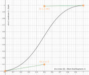
2) There is a mapping of z coordinates (distances from the throat) for these slices that is controlled by a Bezier cubic. On the graph below you see the default setting. This can be changed by a parameter Mesh.ZMapPoints. For the default values it would be:
Mesh.ZMapPoints = 0.5,0.1,0.5,0.99
The numbers are just the coordinates of the cubic control points (x1,y1,x2,y2), normalized to interval <0, 1>.
You can easily setup you own slice spacing by this interactive graph: Desmos chart - Bezier cubic for Z-Map - slide the middle two orange control points.
I think that in most situations the default values will work just fine. You can change that however and maybe it's good to be aware of.
1) There is a parameter "Mesh.DepthSegments" that is well known. It defines the number of "slices" for the mesh and STL. This is also the number of slices written in the coordinate file.
2) There is a mapping of z coordinates (distances from the throat) for these slices that is controlled by a Bezier cubic. On the graph below you see the default setting. This can be changed by a parameter Mesh.ZMapPoints. For the default values it would be:
Mesh.ZMapPoints = 0.5,0.1,0.5,0.99
The numbers are just the coordinates of the cubic control points (x1,y1,x2,y2), normalized to interval <0, 1>.
You can easily setup you own slice spacing by this interactive graph: Desmos chart - Bezier cubic for Z-Map - slide the middle two orange control points.
I think that in most situations the default values will work just fine. You can change that however and maybe it's good to be aware of.
Attachments
Last edited:
- Home
- Loudspeakers
- Multi-Way
- Acoustic Horn Design – The Easy Way (Ath4)