The path length difference is what creates a spherical wavefront. In an OS waveguide, the 0th mode travels along the radial coordinate and normal to ALL angular coordinates. This means that insertion of vanes that are angular coordinates themselves will always be normal to the wavefront and if the vanes are thin enough, then they will do nothing to the 0th mode. They will raise the cut-in for any HOM however, quite possibly pushing them out-of-band.
The thickness is an issue as the vanes need to be thin.
If I'm understanding this correctly:
1) If the vanes are very thin, and the wavefront travels down the waveguide correctly, the wavefront basically won't "see" the vanes. For instance, 337,500khz is one millimeter long. So if you had a vane that's one millimeter thick, the frequencies above 84,375khz won't "see" the vane. The vane is just too small to disturb the wavefront if the wavefront is traveling properly.
2) Now the interesting thing is if the wavefront ISN'T traveling properly. A higher order mode isn't going the right direction, and the vanes may attenuate HOMs.
Then again, the vanes may wreak havoc with the wavefront that's traveling properly, due to the reflections of the HOMs.
Software would probably be helpful here.
Looking at the pictures, what about a "coaxial multicell" horn? I suppose it wouldn't work for some reason, right?
Have you seen the work by Viktor Berstis? In my mind it could be scaled appropriately for the wavelengths involved and shape the wavefront exit out of the throat. Berstis Lens
AES E-Library >> 3D Printed Acoustic Lens for Dispersing Sound
Maybe splurge and buy a resin printer to be able to print small enough?
It's funny, I was going to make a comment about the Berstis Lens, and then I figured that nobody would know WTF I was talking about.
In particular, Jack in Poland spend something like a week 3D printing one of the Berstis lenses, and the real-world results were pretty awful. It seems to confirm what I've noticed in my own experiments with waveguides: basically they hate vanes.
In particular, Jack in Poland spend something like a week 3D printing one of the Berstis lenses, and the real-world results were pretty awful. It seems to confirm what I've noticed in my own experiments with waveguides: basically they hate vanes.
We would probably all agree - just by intuition - that thin enough vanes in a straight tube won't do anything to the fundamental mode when parallel to the tube axis. But it may shift the HOM cut-ins significantly higher. Now within the oblate spheroidal coordinates this is a lot less intuitive but the principle is very much the same. A expect the devil to be in the details.
Last edited:
1) If the vanes are very thin, and the wavefront travels down the waveguide correctly, the wavefront basically won't "see" the vanes. For instance, 337,500khz is one millimeter long. So if you had a vane that's one millimeter thick, the frequencies above 84,375khz won't "see" the vane. The vane is just too small to disturb the wavefront if the wavefront is traveling properly.
You mean "below" I hope. But it's more like 21 kHz. When the vanes thickness is comparable to a wavelength then all bets are off.
Maybe I misuderstand what you mean but a "parallel wall" works only for the tube. There won't be many coordinates sytems where this is actually applicable (I'm sure Dr. Geddes could name them right away) - OS being presumably one of those. The vanes must follow these coordinates exactly to be "invisible".
How did you generate the profile and the vanes? It would be interesting to see the mesh. (Beware that it probably must be a real OS, i.e. with k = 1.)
Haven't you tried the vanes longer?
I took the original contour in Fusion, split it in slices and took the half points and connected them. So probably not the best way to do it.
What would you think the best way to do it is?
Maybe scaling in 1 axis?
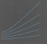
I tried some different configurations with number of vanes and length, but there was always a bump.
And no difference in the HF directivity.
I'm using curcular symetry.
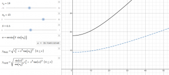
The vanes must follow the angular OS coordinates: OS coordinates
(Slide 'S' to set the angular position. Keep k = 1.)
(Slide 'S' to set the angular position. Keep k = 1.)
Last edited:
Personally, I would try to lead the vanes the a point where the wall curvature drops, which can be approx. 1/3 of the total length of the device (see e.g. Fig.5 in http://www.at-horns.eu/release/OS-SE Waveguide.pdf).
You could try SVG that is supportedI'm giving it another try.
Only wish Fusion's sketch DXF export was directly supported by akabak..
Export an SVG File in Fusion 360 : 5 Steps (with Pictures) - Instructables
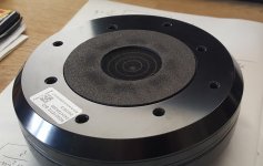
I have this 1.5" 18Sound, which would lend itself quite nicely.... As soon as you mentioned this, I wondered if there's a CD with suitable phase-plug termination to use the ends of the phase plug rings as the start of your vanes - allowing any cavities to be minimized. Otherwise, unless I'm mistaken, this - nice idea - is going to be rather hit and miss with different CDs.
But I'll probably wait for someone who proves it does work at all
")
Attachments
BTW, one would not necessarily need a resin 3D printer for this, IMHO. With a one-perimeter print and a common nozzle it's possible to get to 0.4 mm thickness, perhaps with some additional epoxy coating a little more. The question is how resonant that would be but maybe it won't be critical from the design as long as the pressure would be approx. equal from both sides (?).
- Home
- Loudspeakers
- Multi-Way
- Acoustic Horn Design – The Easy Way (Ath4)