What I don't understand is the stated relation to the size of woofer and WG. A woofer emitting sound at near XO, say a few kHz is mainly radiating from the center of the cone - often it is the coil former that is the most active part. So the size of the radiation surface that is to mate with a WG is rather maybe 1 or 2 inch in diameter.
I suppose in the end the only thing that matters is the DI at XO. V and H.
No?
//
I suppose in the end the only thing that matters is the DI at XO. V and H.
No?
//
...how can you reduce the centre to centre distance
One way is this, it's what I meant when I wrote to "nest the woofer into the horn".

There are better pictures but this was the first that came to hand, shows the basic idea.
If the baffle is moulded as one piece, then the idea can be carried further, clearly.
...the woofer behind a port/slot.. closer to the waveguide with this new center of the driver.
Exactly, I did mention "Danley style" as another option.
My point was that reduced centre to centre is not necessarily the same as smaller vertical horn dimension.
Best wishes
David
Last edited:
Thats wise - moves the interference pattern upwards in frequency
Ideally it is more than simply to move the interference pattern upwards but rather to place it with respect to the crossover frequency so as to maintain pattern control in the vertical plane where it is usually lost.
... I would have put some putty...in order to reduce diffraction
Yes, it was just to show the idea so I didn't have to draw it.
I want to do a nice smooth transition for my own speakers, like moulded rather than carved up.
At some point the woofer starts to impact the horn shape and pattern but it looks possible to reduce C to C substantially before this starts to matter.
In fact a small break up of symmetry should remove the famous "on axis" hole as a free bonus
Of course that can be done with a sufficient round-over/ transition too.
But if it's removed by symmetry breakup then perhaps we can save a little space on the round over.
What I need to do is run sims to find the optimal trade-off but it's slow.
Best wishes
David
Last edited:
Perhaps I should have been more clear: The misconception is the idea that making a waveguide oval by reducing its vertical size to reduce the C-C distance improves the vertical pattern control. In the end it doesn't because of the worsened radiation pattern of the waveguide itself.
I stand by this claim, the rest is a different issue.
- Thinking about it, maybe with a free standing waveguide I would try to put it in a mouth of a bigger "horn" with several smaller woofers in the walls. Of course, the lower the XO frequency, the better.
I stand by this claim, the rest is a different issue.
- Thinking about it, maybe with a free standing waveguide I would try to put it in a mouth of a bigger "horn" with several smaller woofers in the walls. Of course, the lower the XO frequency, the better.
Last edited:
The misconception is...
Ok, that is now clear and we are in accord- smaller vertical dimension just to reduce C to C is a bad idea.
Any comments on my proposal to nest the woofer into the horn and use the C to C interference to maintain pattern control down to frequencies where it is usually lost?
There is a kind of conflict between the domain of "ray" acoustics where wider is wider, and "diffraction" acoustics where narrower is wider, so to speak.
To exploit the C to C distance near crossover to widen the vertical dimension is one of the few ways I can think to reconcile the otherwise incompatible requirements.
Anyone seen this used or analysed, or worked on the idea?
Best wishes
David
Yeah, the Multiple Entry Horn seems to be a successful concept until something better comes up. Multi million (a guess) business here Synergy Horn | Danley Sound Labs, Inc. only thing they are missing is a proper hifi waveguide SH50 looks to be square at the throat and almost worst possible mouth termination, lots to improve.
SH50 looks to be square at the throat and almost worst possible mouth termination, lots to improve.
Last edited:
Is this what you had in mind?Very interested!!
Especially as I can't even open the software! Ha ha

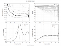
The data is normalized to 15 degrees.
/Anton
EDIT: added legend
Last edited:
What do you feel is missing in the curves I showed? IMHO it could be more CD, but other than that it's pretty good for a horn mated to a cone driver. No?If the DI was low it wouldn't beam like hell
Frankly, I think that such narrow as 50° coverage angle is not really advantageous. Make it 70 - 90° and it will be a lot easier to achieve. And I mean "constant directivity" - beaming is easy and what onni shows is still not a particularly well controlled, IMHO. Probably considerably better than the JMLC though.
/Anton
You just said it - it could be more CD. There was a demand for a 50° CD waveguide for a 1.5" driver. I'm not sure that a device maintaining the beamwidth from ~2 kHz is the answer. Yea, it's not bad, I only don't really see a benefit in using cone driver in such case - I would understand it if you planned to use it much lower, i.e. to use a much bigger waveguide.
Ah, alrightYou just said it - it could be more CD. There was a demand for a 50° CD waveguide for a 1.5" driver. I'm not sure that a device maintaining the beamwidth from ~2 kHz is the answer. Yea, it's not bad, I only don't really see a benefit in using cone driver in such case - I would understand it if you planned to use it much lower, i.e. to use a much bigger waveguide.
The plan is to first print this profile and then make a larger one. My printers limit is 40x40x45 though. I don't think I want it bigger than that any way. Cardioid bass (mids) is an interesting concept IMHO, but the beamwidth of a cardioid is quite wide. The plan was initially to make a wider coverage horn (to mate better with cardiod mids), but I got a lot smoother results for the cone driver when going narrow.
But for a 1.5" compression driver you could get a lot more CD than my results. They tend to be very expensive if you want the crossover below 800 Hz.
/Anton
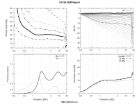
I again tested the effect of throat angle mismatch. It seems that in case of 1" driver it really isn't that critical (the graphs are normalized to 10°). Probably the biggest effect is on the acoustic impedance and respective ripple in absolute SPL (not seen here because of the normalization).
Two extremes -
Flat wavefront connected to 30° throat:

30° spherical wavefront connected to 0° throat:

Two extremes -
Flat wavefront connected to 30° throat:
30° spherical wavefront connected to 0° throat:
Attachments
Yeah, the Multiple Entry Horn seems to be a successful concept until something better comes up. Multi million (a guess) business here Synergy Horn | Danley Sound Labs, Inc. only thing they are missing is a proper hifi waveguide
The SH50 is so large, the termination doesn't really matter.
This was something I realized on this thread I made:
What Do Roundovers Do?
I tried adding a roundover to my big Unity horns, about 24" in diameter, and it basically made no difference. (Okay, admittedly there was a difference of about half a dB at some frequencies.)
Basically the termination of a horn is a lot more important if the horn or waveguide is small.
I'm not sure I would agree on that. Maybe it doesn't make much difference if there's a lot of other diffraction going on but in my experience the bigger size doesn't make the termination less important. I would say that the better the waveguide from throat to mouth the better must be the termination to maintain that quality.
Sure, I can define any source shape (in shape and amplitude), connected to virtually anything.Re: HOM. Are you in now control from driver->throat->mouth of these in the sense that you can simulate and see a driver/horn combo which produce a lot of HOM and one that HOMs are (almost?) absent?
//
- Home
- Loudspeakers
- Multi-Way
- Acoustic Horn Design – The Easy Way (Ath4)