For me the beaming is maybe the most anoying attribute of a loudspeaker I can imagine, once there are no audible resonances through the midrange. But OK, that may be subjective. It has also a detrimental impact on power response if the direct sound is supposed to be flat, but that may be subjective also. I just can't stand beaming sources anymore so for me it is important.
As usual, I completely agree with you.
I wouldn't say it's clearly so.
Since we move around the room horizontally but rarely jump metres vertically it's far from obvious that the horizontal and vertical directivity should be the same.
And since a typical multi-way speaker has the horn mounted above the woofer there are interference issues in the vertical that do not occur in the horizontal.
So I see no obvious reason why the optimum shape should be axisymmetric.
In fact, since the requirements are different it seems unlikely that identical horizontal and vertical profiles would be optimum.
If we do decide on different vertical and horizontal profiles then I can't see why an ellipse is clearly optimal.
It's just one arbitrary curve after all, albeit a simple one.
The woofer does not have different vertical and horizontal coverage so why is matching it not important? And the vertical lobing issues will be present no matter what the shape. My studies show that they get worse if the vertical is narrowed, not better.
And an ellipse is not "axisymmetric".
You did mention it, I remember because I was curious about pictures or further information but you didn't post any AFAIK.
Still would like to see more about this.
Best wishes
David
I'll see what I can find. Remember that much of my work is decades old and finding relevant data is not like finding your car keys.
Indeed, a free standing was one of the goals. And you really cannot compare a waveguide like an OSWG with a "long" horn like the spherical wave horn. Beaming is relative and by far not the most important fact. This new design reduces the beaming considerably. BTW, if the flare rate of the spherical wave horn is increased the horn would open faster with less beaming but this was not the goal. We also simulated the OSWG with ABEC3 as a free-standing horn and the results were more than discouraging. The wave fronts were looking terrible and so far as I remember also JMLC showed a similar behavior in one of his presentations.
I made JMLC horn with "curved mouth" for coaxial loudspeaker. Its design resembles your Spherical wave horn with the difference that JMLC horn has hyperbolic flare (Fc=900Hz, t=0.5).
Vertical plane ------------------------------------------Horizontal plane

ABEC3 simualtions @3.9kHz.

The beaming was noticeable (from ~60deg @1kHz to ~ 20deg @10khz) both in the simulated and measured results. There were some disagreements the vicinity of the compression driver resonance at ~2khz. However, above 2 kHz the results agree very well. The beaming should disturb the diffuse field. I suppose, that your Spherical wave horn should too exhibit significant beaming.

Another interesting thing is that radiation resistance in the particular JMLC design is slightly reduced above ~4kHz (minimum value is at ~9kHz). While reactance in the same frequency range exhibit both mass- and spring- like behavior. It is quite unusual at the higher frequencies. It seems that the "curved mouth" design further contributes to HOMs generation
 .
.
Last edited:
Another interesting thing is that radiation resistance in the particular JMLC design is slightly reduced above ~4kHz (minimum value is at ~9kHz). While reactance in the same frequency range exhibit both mass- and spring- like behavior. It is quite unusual at the higher frequencies. It seems that the "curved mouth" design further contributes to HOMs generation
Good data, thanks.
Yes, this is unusual to the point of being questionable. I've seen this kind of thing in numerical solution as they reach the limits of their mesh size. It could be a numerical aberration.
@ Dmitrij_S
You should check this site. JMLC is better with t=0.707:
BEM Simulations
I will not disturb this thread with my results but the beaming can be reduced in the horizontal plane what was intended. And I also cannot confirm the imp. hole you receive.
The roll-back should reduce HOMs. JMLC commented several times about this topic and also his own measurements supported this.
Patrick, didn't you ever tried to simulate the M2 horn to see what it's actually doing? With your modelling capabilities, it should not be a problem.
- Or, is somewhere a raw measurement (the complete polars) of the M2 horns to see? I haven't seen any.
Oh definitely, and I 3D printed quite a few.
What I found is that Sprinkle is right:
"The second thing we did was use a blending geometry—there are no straight lines, you’ll notice—that has a generally decreasing radius,” he continues, “forming an infinite number of reflections, and the net effect is that it smears the reflections coming back down the horn and negates them."
Basically sound hates symmetry; you want those waveguides to break up the symmetry. Ideally the phase plug would do it too; note that all the JBL ring radiator phase plugs are asymmetric.

The newer waveguides are way less "aggressive" with the asymmetry than the M2. With the M2 style, with the prominent "beaks", I found that it didn't perform as well as the progressive transition waveguides from JBL. Basically you want *some* asymmetry, but not the crazy protruding "beaks" of the M2.
Last edited:
Good data, thanks.
Yes, this is unusual to the point of being questionable. I've seen this kind of thing in numerical solution as they reach the limits of their mesh size. It could be a numerical aberration.
O course, I forgotten to mention the maximum mesh size I set was 10mm.
Performing BEM simulations I was not sure how to set correctly an interface splitting the BEM object into internal an external sub-domains. I set the interface as depicted by semi-transparent mesh in the picture below. Now I doubt, wouldn't it be better to choose the shape of the interface so that it would be tangent to the mouth
 . Interestingly, is there any rules how to split an object into internal and external sub-domains to get correct results in BEM external radiation problem ? Perhaps this is where additional error comes from ?
@ Dmitrij_S
You should check this site. JMLC is better with t=0.707:
BEM Simulations
I will not disturb this thread with my results but the beaming can be reduced in the horizontal plane what was intended. And I also cannot confirm the imp. hole you receive.
The roll-back should reduce HOMs. JMLC commented several times about this topic and also his own measurements supported this.
Thank you for the link. I have not seen it before.
As regards the "impedance hole", I'm not sure if this is a peculiarity of the horn or is it some kind of numerical simulation error.
Last edited:
O course, I forgotten to mention the maximum mesh size I set was 10mm.
Performing BEM simulations I was not sure how to set correctly an interface splitting the BEM object into internal an external sub-domains. I set the interface as depicted by semi-transparent mesh in the picture below. Now I doubt, wouldn't it be better to choose the shape of the interface so that it would be tangent to the mouth
The 10mm inner horn mesh size is fine.
The inner/outer split should be something like this. I moved the mouth interface subdomain boundary so you can see it, but it actually sits at the horn apex even if there is rollback.
Attachments
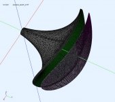
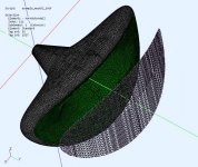
Did you change the inner horn wall impedance in any way? It is rendered green which means it hasn't a default setting (100% reflective), IIRC. Or is it green because it's in the interior subdomain? Now I'm not sure. I first saw a green boundary after I changed the wall impedance....As regards the "impedance hole", I'm not sure if this is a peculiarity of the horn or is it some kind of numerical simulation error.
I have not found much differences between different interface shapes, some may be slightly better than another in minor numerical aberations but nothing like what you show. From the manual it's also clear that it shouldn't make any difference in principle. Only avoid very sharp angles, but that holds everywhere. I don't think the interface boundary itself could be the cause here.
Last edited:
Did you change the inner horn wall impedance in any way? It is rendered green which means it hasn't a default setting (100% reflective), IIRC. Or is it green because it's in the interior subdomain? Now I'm not sure. I first saw a green boundary after I changed the wall impedance.
I have not found much differences between different interface shapes, some may be slightly better than another in minor numerical aberations but nothing like what you show. From the manual it's also clear that it shouldn't make any difference in principle. Only avoid very sharp angles, but that holds everywhere. I don't think the interface boundary itself could be the cause here.
I didn't change the wall impedance, it is set by default. Only the color of the walls was changed. It seems that dr. Gedddes was right, the problem was too coarse mesh (10mm). With a finer mesh (5mm) the "impedance hole" disappeared.
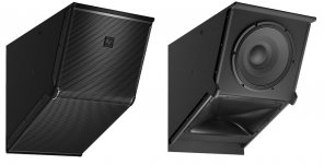
Is it a difference between this:
Tech Focus: Variable Intensity (VI) – ProSoundWeb
and straight waveguide tilted?
Tech Focus: Variable Intensity (VI) – ProSoundWeb
and straight waveguide tilted?
Attachments
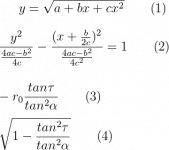
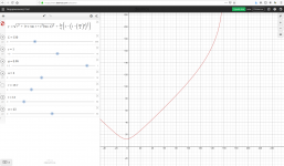
I came across my older notes so here it is:... You can try to convert my OS formula to the first form - you'll see where the center is and what the semi-axes are.
Eq (2) is a rewriting of (1) and from that follows that to take a throat angle (tau) into account, the contour must be shifted in x coordinate by (3) and its scale multiplied by (4). It is all incorporated in the "modified" OS formula.
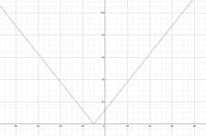
- If one wanted to have a throat angle the same as a coverage angle, it would (surprisingly) collapse into a cone
Attachments
Last edited:
Also note that the maths doesn't prevent you from a throat angle even bigger than the coverage - see what happens
Link to the online graphing of this example: Desmos | Graphing Calculator
Link to the online graphing of this example: Desmos | Graphing Calculator
Attachments
Last edited:
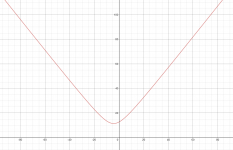
BTW, for those who would like to fiddle interactively with the last OSWG-SE formula, this is a great tool (angles in degrees): OSWG-SE / Desmos | Graphing Calculator
- Note that x is supposed to be limited to [0, L].
- Note that x is supposed to be limited to [0, L].
Attachments
Last edited:
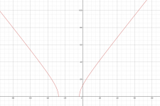
I guess it should be more like this: Desmos | Graphing Calculator
For s = 0 you have a pure OS. Increase it to add more of a termination.
- Together with a cone of the same coverage angle: Desmos | Graphing Calculator
(You can observre the effect of a different throat radius (r) on the contour.)
For s = 0 you have a pure OS. Increase it to add more of a termination.
- Together with a cone of the same coverage angle: Desmos | Graphing Calculator
(You can observre the effect of a different throat radius (r) on the contour.)
Last edited:
- Home
- Loudspeakers
- Multi-Way
- Acoustic Horn Design – The Easy Way (Ath4)