Earl already mentioned this idea years ago: Poor man's plane-wave tube?
I guess that gated impulse response(s) would be the input data.
Correct, and you can see how much interest has evolved in the last 7 years. We still have no idea what we are actually dealing with in a compression driver.
Has anyone tried to build a 3D model of an "ideal" (replacement) phase plug for an OS-type waveguide?Someone mentioned earlier in this thread the possibility of making phase plugs from photoresin printing. From what I remember, JBL actually ended up making phase plugs using this method for production components (I think for one or two of their beryllium diaphragm compression drivers).
Given a tool like the Formlabs Form 3, homemade phase plugs are not out of the question.
evanescent waves...apply to audio?
Yes, the maths is essentially the same, just that optics is more studied.
So if you looked it up on, say, Wikipedia then that is the example you will find.
Best wishes
David
had to ask and i've often seen optics theory "borrowed" to analyze/study acoustics i'm just not certain if it's correct, and yes i'm aware it's wave theory and perhaps my lack of knowledge is what leads me think there are differences in how they behave despite the analogy.
so evanescent waves the the case of plain wave tube is what?
so evanescent waves the the case of plain wave tube is what?
Last edited:
..often seen optics theory "borrowed" to analyze/study acoustics i'm just not certain if it's correct, and yes i'm aware it's wave theory...
The classical wave equation is essentially identical for the two cases so they behave similarly.
The main exception is that optics has the complication that waves can be polarised, not applicable to acoustics.
Obviously there are limits, the acoustic medium is not an idealised continuum but composed of air molecules, quantum effects in optics, and so on.
But for practical purposes it's pretty close.
so evanescent waves the the case of plain wave tube is what?
My concern was that the non flat wave-front component would correspond to modes that would not travel down the wave tube, only decrease exponentially away from the source and rapidly become undetectable.
When Marcel posted the link to the earlier PWT thread I noticed that Earl also raised the issue of evanescent waves.
So my concern seems to have had some foundation.
I still don't have a clear idea of how this will work out in practice.
My first impression was doubt that it was doable.
But Earl says he worked it out so I may well be mistaken.
I would like to see more detail.
Best wishes
David
yes i do have to study more math and spend less time postulating under the influence of scotch...
are "polarization" and "phase" not super secret evil twins?
it bothers me when a math analysis or treatise contains statements like" for the formula or equation to work one must ignore..." or "it can only be solved in one dimension..." makes me feel cheated and sometimes duped...but that's a personal peeve.
and this may be a misguided concept but "time" (speed of propagation) is where light and sound are to me quite different, no?
Now I'm lost. I gather you suggest that one should in fact capture these effects to see the complete picture of the wavefront. Earl seems to say the opposite: "1) the mic should not be too close to the aperature connection because of evanescent wave effects. Further is better, but that means a longer tube". It's over my head anyway...My concern was that the non flat wave-front component would correspond to modes that would not travel down the wave tube, only decrease exponentially away from the source and rapidly become undetectable.
The classical wave equation is essentially identical for the two cases so they behave similarly.
The main exception is that sound is a slow propagation phenomenon

are "polarization" and "phase" not super secret evil twins?
No, different phenomena.
speed...quite different, no?
Different speed just scales the time up or down, this is trivial in terms of the physics.
The point is that the wave equation is essentially identical so the behaviour is similar.
It is actually a bit remarkable that two such different situations should have so similar mathematics.
Now I'm lost...Earl seems to say the opposite: "1) the mic should not be too close to the aperature connection because of evanescent wave effects. Further is better..."
I think the context is that Earl's comment was about the normal use of a PWT to study frequency response.
"Further is better" to minimise the evanescent wave effects, which are an unwanted complication in this case.
Whereas my comment was about the use of a PWT to study the deviation from flatness of the driver wave.
In this case I think the evanescent wave effects are where the deviation is most easily studied.
So my query to Earl was if this was how his idea worked.
But it's still not clear to me what his technique actually is, so don't take my post as a recommendation.
Best wishes
David
Last edited:
...the evanescent wave effects are where the deviation is most easily studied...
Dave, could you recommend a book describing the math of the evanescent wave effect ? To me it is not evident the nature of the effect in acoustics.
not so sure about polarization and phase being different....
Polarization of light, linear and circular (video) |
Khan Academy
https://aip.scitation.org/doi/full/10.1063/1.5110673
and this is why frequency response charts are dubious to me they contain no phase information (it would make for really messy charts)
well time to open a bottle of scotch and do some physics reading.
I still don't have a clear idea of how this will work out in practice.
My first impression was doubt that it was doable.
But Earl says he worked it out so I may well be mistaken.
I would like to see more detail.
Best wishes
David
I think the context is that Earl's comment was about the normal use of a PWT to study frequency response.
"Further is better" to minimise the evanescent wave effects, which are an unwanted complication in this case.
Whereas my comment was about the use of a PWT to study the deviation from flatness of the driver wave.
In this case I think the evanescent wave effects are where the deviation is most easily studied.
So my query to Earl was if this was how his idea worked.
But it's still not clear to me what his technique actually is, so don't take my post as a recommendation.
Best wishes
David
Dave has it correct here. If one is only interested in the plane wave response, as usual, then evanescent waves are a confounding factor. But in the modal decomposition, they may be essential. It's all in the context.
And thanks Mabat for that excellent link on evanescent waves. Nowhere like Penn State for good foundations in acoustics.
So back to our problem. Clearly I can not show the precise math since this kind of forum does not lend itself to mathematical expression, but here is the gist:
We have a vector of unknown modal participation values (complex) M, and a vector of measured wall pressures P (complex). P should be > M, but is only required to be equal to M.
Then what has to be true is that there is a matrix R of size MxP such that:
R*M=P
Then M = (R)^-1 * P
It turns out that R can be evaluated as the transfer function of each mode to each wall pressure. This is not hard to evaluate from the basic solutions of the duct wave equation. These are all known and readily available as Bessel functions, the lowest one being a simple plane wave down the tube, a pure delay. Higher order modes are more complicated, but still readily solved.
The matrix inversion for a square matrix will be virtually guaranteed to be singular at one or more frequencies, but an NxP size matrix can always be inverted with SVD (Singular Value Decomposition) an extremely powerful technique in numerical calculations (although SVD for complex matrices is a bit obscure.) The larger P is, the more stable the resulting solutions M will be. This would all need to be worked out in practice, mostly for stability.
If I can find my documents from that time (about 20 years ago) I will try and post them, but experience has shown me that as the docs get older they get less available.
Has anyone tried to build a 3D model of an "ideal" (replacement) phase plug for an OS-type waveguide?
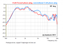
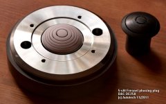
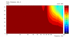
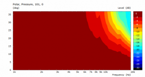
I've tried in 2011.
Attachments
care to share more details of that saga?
Improves Chinese driver but not necessarily a good one like BC
- Home
- Loudspeakers
- Multi-Way
- Acoustic Horn Design – The Easy Way (Ath4)