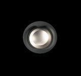
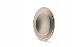
Although not a compression driver with its associated suspension & pressure issues, Focal succesfully used foam in a single suspension ring in the T120 Tweeter. No aligning/centering problems for the voicecoil assembly to my best of knowledge.
So the picture in post 1997 may at least be worth experimenting with.
So the picture in post 1997 may at least be worth experimenting with.
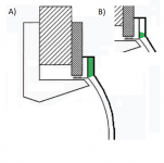
Well the picture as shown is really out of scale as the actual suspension would be thiner and wider so the shear resistance may be not so low, perhaps. Anyway, if it could be stiffer than silicone, it could be made of an epoxy resin I know of that can be mixed for being elastic (60 Shore A). That would make quite a good lateral stiffness I guess.
Thanks for the comments. I will think about it. Foam was the first material that came to my mind but it may be difficult to make it in the required thickness.
Thanks for the comments. I will think about it. Foam was the first material that came to my mind but it may be difficult to make it in the required thickness.
Last edited:
Anyway, if it could be stiffer than silicone, it could be made of an epoxy resin I know of that can be mixed for being elastic (60 Shore A). That would make quite a good lateral stiffness I guess.
You can get any shore hardness you want with 2k poly.
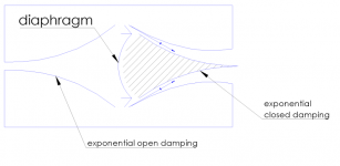
The issue is the difference between materials in shear and in compression. With an in-line suspension, the material is always in compression so it works with good lateral stiffness. But any material in shear is far weaker, so using it in shear yields very low lateral stiffness.
What one wants is (very!) high lateral stiffness with low axial stiffness. This is ideally achieved with normal suspensions through the sin(theta) mode of stretching. It is going to be hard to beat this well thought out "classic" approach.
Although not a compression driver with its associated suspension & pressure issues, Focal succesfully used foam in a single suspension ring in the T120 Tweeter. No aligning/centering problems for the voicecoil assembly to my best of knowledge.
So the picture in post 1997 may at least be worth experimenting with.
Focal initially used foam and switched to Supronyl for later generations.
In the current M-shaped inverted dome tweeters, a Poron suspension is used.
Both the foam and Supronyl rings are available as replacements parts.
Attachments
-
 tweeter-m-focal-responsve.jpg32 KB · Views: 126
 -
 M-shaped tweeter.jpg54.3 KB · Views: 121
 -
 Die Polyamide.jpg254.5 KB · Views: 135
 -
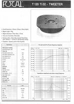 FOCAL_TWEETER_T120TI02.jpg710.2 KB · Views: 379
 -
 FOCAL_TWEETER_T90TI02.jpg668.6 KB · Views: 394
 -
 FOCAL_TWEETER_TC120TDX.jpg265.5 KB · Views: 404
 -
 FOCAL_TWEETER_T90K.jpg655.3 KB · Views: 412
Marcel - maybe you could sim something like we555 but with new hacks.
This is a splendid suggestion J.
Perhaps, I should donate a NSD driver then
")
Then there's an option of keeping the existing suspension and using a soft silicone just as a filler to isolate the suspension from the compression cavity. It would add some moving mass I suppose. Not so sure about any other effects it might have, being much softer than the suspension. Or some foam ring.
Attachments
Last edited:
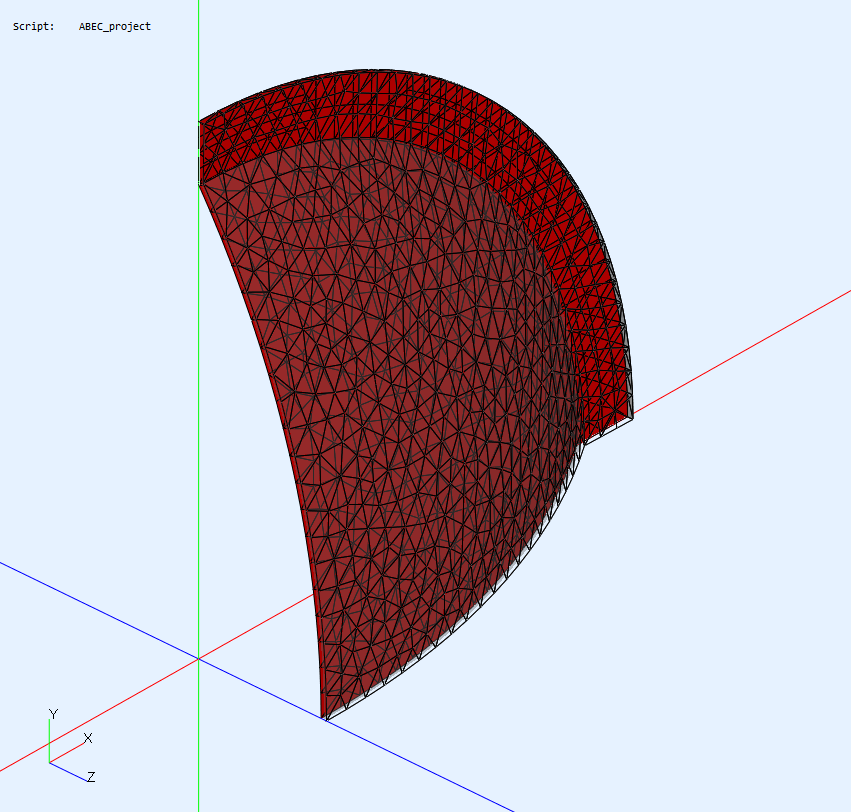
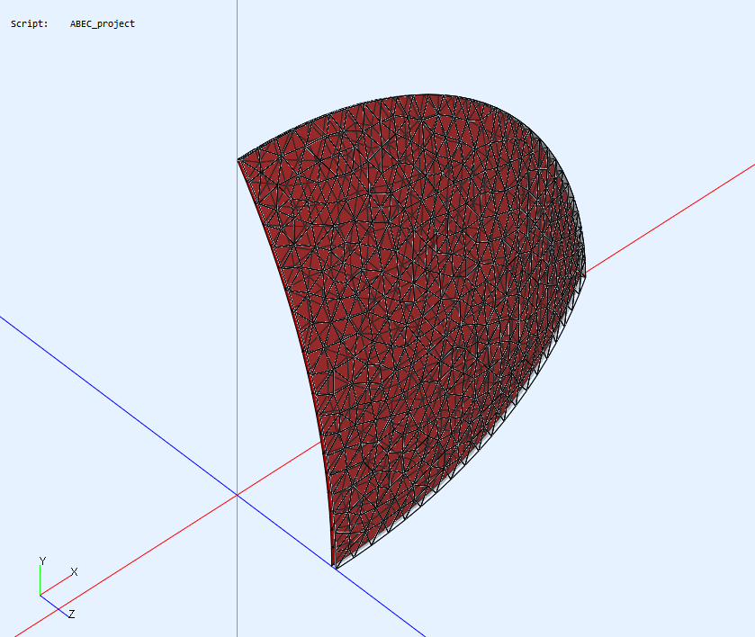
mabat: Thanks for all support. I´m getting familiar with everything, and while it is a lot, it is very nice and I mostly understand. Now, I would like to make my own waveguides weirdly shaped. Not going to ask for details for this, I will find out.
I miss one thing though - when I load your mesh file alone, it is just one quarter of the waveguide. I do not see anywhere in the files, where it is assembled into four segments in the ABEC SW. Could you give a hint?
Thank you.
I miss one thing though - when I load your mesh file alone, it is just one quarter of the waveguide. I do not see anywhere in the files, where it is assembled into four segments in the ABEC SW. Could you give a hint?
Thank you.
That's on purpose, of course. The symmetry is defined in "Control_Solver" (solving.txt) as "Sym=xy". You can also hide the "redundant" parts by the "Views - Symmetries" checkbox in the GUI.I miss one thing though - when I load your mesh file alone, it is just one quarter of the waveguide. I do not see anywhere in the files, where it is assembled into four segments in the ABEC SW. Could you give a hint?
Thank you.
That's also the limitation for now. This symmetry is enforced for any shape you create, i.e. only the first quadrant is taken and mirrored this way. This might change in a next version of the tool.
Then there's an option of keeping the existing suspension and using a soft silicone just as a filler to isolate the suspension from the compression cavity. It would add some moving mass I suppose. Not so sure about any other effects it might have, being much softer than the suspension. Or some foam ring.
If the gap at the rim is an issue for you, and I am not sure that it is such a big problem, then what you suggest here is the way to go. But it may add more problems than it corrects.
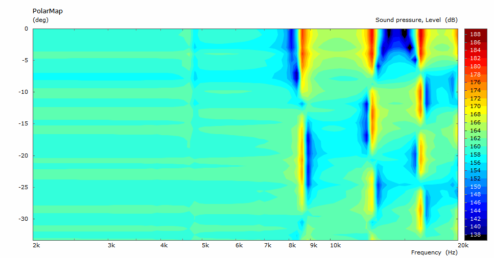
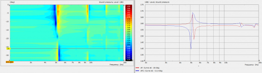
Here is the issue. I made simulations of the compression cavity for different suspension contributions.
Geometry parameters:
Voice coil diamter: 75 mm
Suspension length: 5 mm
Diaphragm height (draw): 11.25 mm
Cavity gap: 0.5 mm
1) Cavity including the suspension
From the worst to the best:
1-1) No suspension contribution
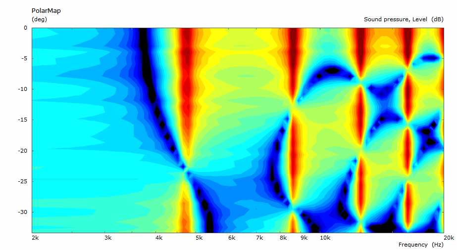
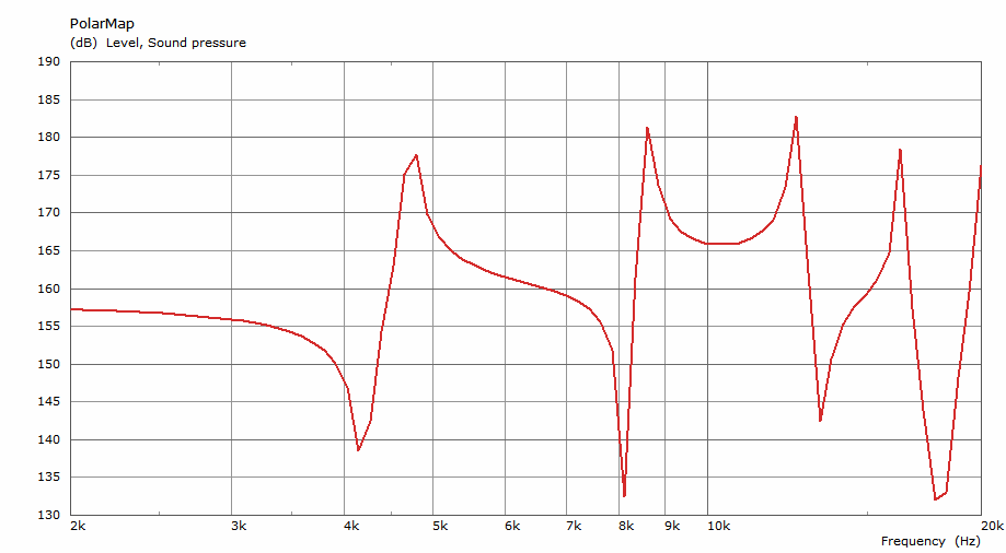
1-2) "Close-to-real" scenario: Suspension divided into two rings of the equal widths; excursion weights: 0.75 and 0.25
1-3) Whole suspension driven to full excursion (i.e. uniform axial motion across the cavity)
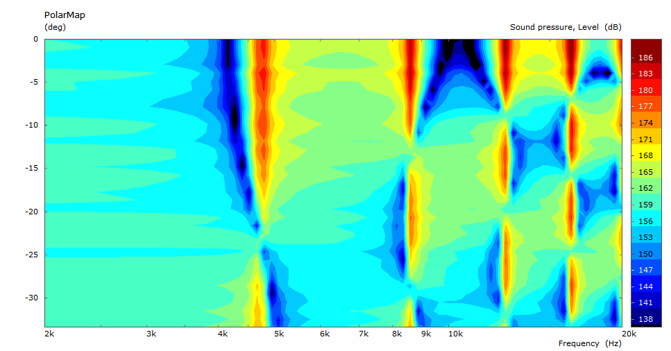
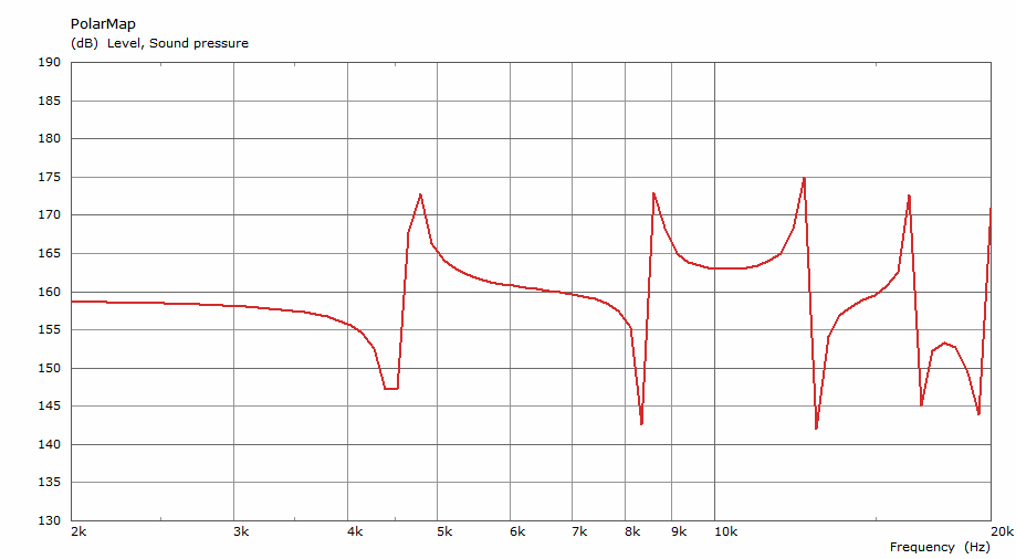
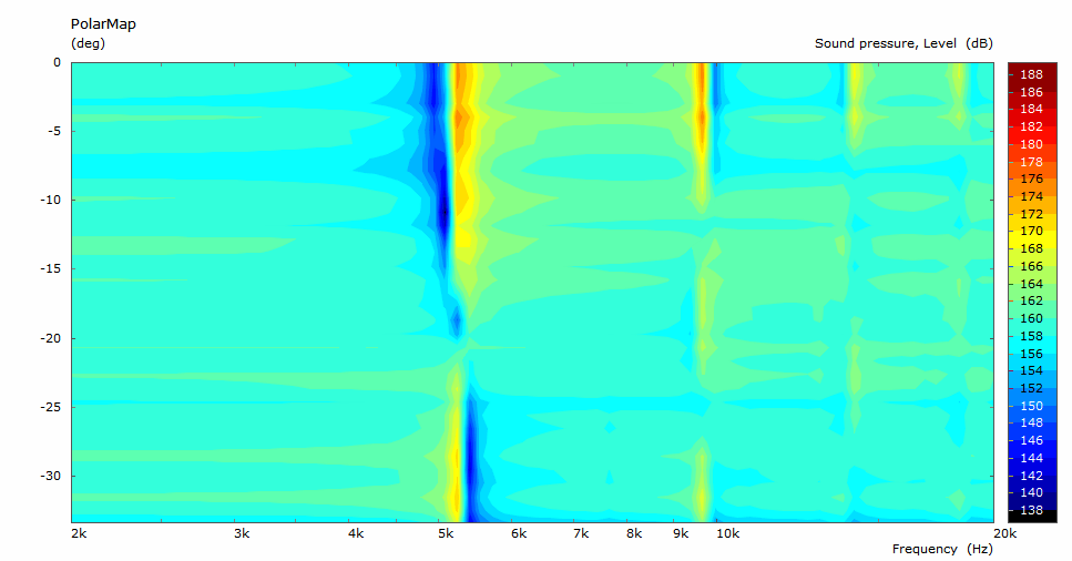
2) Cavity with the suspension isolated
Geometry parameters:
Voice coil diamter: 75 mm
Suspension length: 5 mm
Diaphragm height (draw): 11.25 mm
Cavity gap: 0.5 mm
1) Cavity including the suspension
From the worst to the best:
1-1) No suspension contribution
1-2) "Close-to-real" scenario: Suspension divided into two rings of the equal widths; excursion weights: 0.75 and 0.25
1-3) Whole suspension driven to full excursion (i.e. uniform axial motion across the cavity)
2) Cavity with the suspension isolated
The nulls are suspiciously deep (& look resolution limited). Makes me ask: does the model include damping?
I expect thermo-acoustic damping to be significant in a gap of 0.5mm.
It might be good if someone with the right experience would comment if the equivalent resonances are seen in practice. I don't recall seeing corresponding features in the few CDs I've measured.
Ken
ps. apologies if that's been discussed, I've only skimmed the last 500 posts of what's become an interesting thread.
There's no damping, I didn't try, but that's not the point at the moment I think.
The reason why you don't see these peaks and nulls in practice may be because that in a properly designed phase plug these tend to cancel out - see the picture below (and yes, it is resolution limited but overall it can be clearly seen from that).
The less disruption, the better - the easier the phase plug design.
Attachments
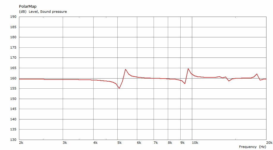
Maybe what is interesting is that if the whole suspension vibrated axially (i.e. was in fact not a suspension but a continuation of the diaphragm), the excitation of the lowest mode would be almost nil -
Cavity without the suspension:
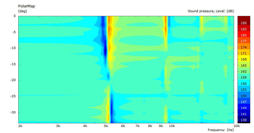
Cavity including the uniformly driven "suspension":
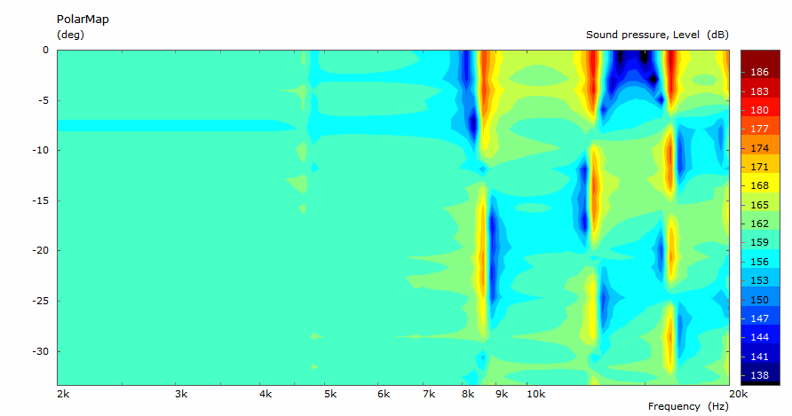
Cavity without the suspension:
Cavity including the uniformly driven "suspension":
Last edited:
- Home
- Loudspeakers
- Multi-Way
- Acoustic Horn Design – The Easy Way (Ath4)