Hi,
I am wondering if anyone here has tried to compare their simulation result and actual experimental results.
In my latest project, I simulated a BR speaker with a 4" driver. I chose a box frequency much lower than Fs. The simulation goes from 100Hz to about 50Hz with a slow decline, maybe about 6dB before it drops off rapidly for going below port tuning frequency. Port tuning frequency about 60Hz. But when I built and measured it, I have a massive drop in frequency between 100Hz to 50Hz.
Any idea what could have caused it?
Several theory of mine, hopefully somebody with more experience can chime in.
1) The measurements are off - I am doing it in room with a quasi anechoic technique using Dayton omnimic. Quasi anechoic is notoriously unrealiable in the room due to room modes
2) My port is located at the bottom, I suppose the simulation may assume that the port in in front.
3) The simulation doesn't take into account the rise in impedance, assume that the power delivery is always constant, whereas in real circumstances, there is two impedance peaks where power delivery is minimal
Thanks in advance for all your thoughts and suggestions.
Oon
The port location does not matter at those frequencies as long as there is nothing obstructing the port. If your port is at bottom, you may need to lift the box to get sufficient clearance between port and ground.2) My port is located at the bottom, I suppose the simulation may assume that the port in in front.
The simulations assume a constant voltage source and thus takes are of impedance variation, the impedance varies quite a lot as compared to Re. If impedance variations were not taken into consideration then the simulations would be useless.3) The simulation doesn't take into account the rise in impedance, assume that the power delivery is always constant, whereas in real circumstances, there is two impedance peaks where power delivery is minimal
Little bit of result variation between simulation and reality is expected and of not much consequence.
Measure outdoors on ground and compare with a half space simulation.
Hi GM,
Thanks for the information, so there would be some difference if the port is below, since the so called front component is significantly less. In which case the increase in amplitude due to constructive inteference when both port signal and driver signal combined is also be significantly less. Would that be correct?
That aside,
Does anybody know what perceptible difference in bass quality in front firing port, rear firing port and bottom firing port.
Theorectically, they should be the same, as the wavelength is very long, and it should be the same everywhere. But of course that is only theory.
Oon
Greets!
It depends as wonderfulaudio noted; the actual vent output WLs are huge [344/pi/60 = ~1.825 m diameter], so unless the woofer is further away than typical or the floor is padded/carpeted it will depend on how you measured it, room interaction and how accurate your mic is down low.
Also, did you sim with published specs and if so, is it a brand known for accuracy?
FWIW, I was taught to measure drivers at < ~1/4" [.635 cm] from the dust cap, vents, horns, etc., with the mic centered on axis inside ~1/4" [.635 cm], i.e. a 1/2 WL of ~27,120 Hz, to take the room out of the 'equation'.
GM
My experience is that if the port and driver are relatively close, eg, <1/4 wavelength at tune, it generally doesn't matter with conventional designs. My first preference based upon a number of factors is bottom ported, but it's been a while since I did a BR speaker. The next one I have designed on paper is bottom firing.That aside,
Does anybody know what perceptible difference in bass quality in front firing port, rear firing port and bottom firing port.
Theorectically, they should be the same, as the wavelength is very long, and it should be the same everywhere. But of course that is only theory.
Oon
The drooping response will sound like less than a quarter as loud ( due to the way our hearing at low frequencies works at low sound pressure levels ) See: Robinson–Dadson curves - Wikipedia Robinson–Dadson curves - WikipediaHi,
I am wondering if anyone here has tried to compare their simulation result and actual experimental results.
In my latest project, I simulated a BR speaker with a 4" driver. I chose a box frequency much lower than Fs. The simulation goes from 100Hz to about 50Hz with a slow decline, maybe about 6dB before it drops off rapidly for going below port tuning frequency. Port tuning frequency about 60Hz. But when I built and measured it, I have a massive drop in frequency between 100Hz to 50Hz.
Any idea what could have caused it?
Several theory of mine, hopefully somebody with more experience can chime in.
1) The measurements are off - I am doing it in room with a quasi anechoic technique using Dayton omnimic. Quasi anechoic is notoriously unrealiable in the room due to room modes
2) My port is located at the bottom, I suppose the simulation may assume that the port in in front.
3) The simulation doesn't take into account the rise in impedance, assume that the power delivery is always constant, whereas in real circumstances, there is two impedance peaks where power delivery is minimal
Thanks in advance for all your thoughts and suggestions.
Oon
At an 80dB midband level around 1khz, you need the bass at 60 hz to be 100 dB, or 20dB louder to be perceived at the same level. For highest efficiency, tune at Fs or higher. Not to say that one can't tune below that, though you are in the compliance controlled region ( not mass controlled ) and if the suspension is tight, you may not get near what the simulation says.
Also, you must use a proper high pass filter with a ported enclosure, below tuning the driver will be unloaded, and oscillate without control. Quasi-anechoic, can you elaborate? Are you remote from walls, floor and ceiling, with the microphone 1/4" to 1/2" or so from the dustcap? This method will not show the port contribution, the output from the woofer would be much louder. Forget the mic for a moment, place the box with the driver face up on the floor, and play some music through it. Does it have any bass? You may have other issues with signal chain, or simply being in a null in the room. Check the port tuning frequency with a signal generator, you may be way off target. ( if you haven't measured it and are assuming )
Did you account for the lost volume of the port in the actual construction size? 60 hz tuning with a 4" driver is an optimistic, limited SPL application only. Like boombox or small bluetooth speaker application, where nearfield listening takes place. Sealed, a 4" driver is good for 75 dB @1 meter @ 1.08 mm excursion ( one way ) or 2.16 mm p-p, driven with a 60 hz sine. Piston Excursion calculator In a ported enclosure, the excursion maxima above tuning is ~1.5x your tuning frequency.
Choosing 60 hz tuning, ~ 90 hz would be your excursion maxima, assuming roughly 2 mm P-P clean excursion ( 1 mm one way) limits your maximum output to approximately ~ 81 dB peak @ 1m. No allowance for dynamic range head room is made, nor is there a reduction in the LF. ( drooping response, possible coil offset, rock hard suspension, motor asymmetries, etc ) If you have a drooping anechoic response, placement near intersecting boundaries will add back some gain. ( floor / wall, ceiling / wall, etc ) Placed in free space, the small driver with drooping response will seem very underwhelming. Hope that helps.
Oon
Can you post the Omnimicmeasurement and the simulation?
Also, the driver you are using.
Regards
Mike
Hi,
Sorry for the late reply. Have been a bit busy lately.
The speaker driver is a Faitalpro 4Fe32
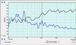
The freq response by Omnimic measurement shows a 12db drop from 150Hz to 50Hz. Distance from mike to speaker is about 50cm. The simulation (woofer box model and circuit designer by Jeff Bagby) shows a drop of about 6db only.There is also a further drop of 6db at port tuning frequency (circa 60Hz). I had also verified by impedance measurement using the DATS system the port tuning frequency is at 60Hz.
The volume of the cabinet is about 3l and is a 9inch sphere.
the cabinet is a wooden sphere of about 9 inch in diameter. The driver is facing the front and the port is at the bottom. The distance between port and bottom surface is about 1 inch.
Thanks.
Oon
Attachments
At an 80dB midband level around 1khz, you need the bass at 60 hz to be 100 dB, or 20dB louder to be perceived at the same level. For highest efficiency, tune at Fs or higher. Not to say that one can't tune below that, though you are in the compliance controlled region ( not mass controlled ) and if the suspension is tight, you may not get near what the simulation says.
Thanks for your lengthy reply. Really appreciate it. Yup, I did have a high pass filter at about 40Hz to reduce power below port tuning.
This makes sense, I am not familiar on the basis is the model and assumptions. But tunign below Fs is probably not what a lot of people will do and the inacuracy of the model might be the cause of deviation.
I am also most concern about the drop at port tuning, as if the port not working at all.
I will try to measure while barricading the area so the the port energy only points front and see if it makes any difference.
OOn
Seems to me the agreement of sim and mic are quite good. A whole lot better than I'd expect.
On the other hand, the only measurement that counts in the end is made at your listening chair. Domestic room acoustic influences will overwhelm the little variations in up-close mic measurements. So then you need to introduce DSP to fix things since it would only be random luck if the bumps in the sim were helpful or harmful to the room response.
The smart future methodology will be to assess the room first and then do a sim that recognizes drivers, boxes, and rooms in the mix.
B.
Last edited:
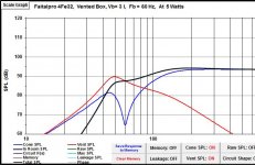
The speaker driver is a Faitalpro 4Fe32
The freq response by Omnimic measurement shows a 12db drop from 150Hz to 50Hz.
Your port tuning is too low (left plot-black trace). Tuning to 80Hz will give you a F3 of 83Hz (center plot)
Or better still, change it to a Sealed Box (right plot F3=142Hz) and cross over to a woofer for bass.
Attachments
Hi Michael,
Thanks for the simulation, i didn't mention earlier that i tried another box at 80 Hz and it sounds better and sims better.
Simulation based on the worksheet i have and your differs by a about 2db at 60 Hz. But iwill still be happy if i had a result that was anything close to what you were getting.
I wanted more bass extension, and one way of achieving it is by dropping the port frequency and giving it a small 3-6 db boost by dsp. If had the based on your simulation, i would add a 4 db boost electronically at 60Hz, i would achieve a frequency response of -3db at 60Hz. Would have been more than adequate for me.
However kn my case it was 12db down at 50 Hz and 18db down at 60Hz. That is not realistic to correct electronically.
Even at my other box where i tuned it to 80Hz, it was down at -6db at 70Hz but there was a big dip at 80Hz port tuning frequency.
I can't quite undertand the cause of the dip. Although for the simulation to be off might be because of as what another poster has mentioned, that port tuning below Fs is quite inaccurate..
Oon
It seems as if the port is not doing its job. I stuffed the box with acoustastuff lightly. Could that be the source of the problem? Maybe i should use a absorbent material that is only on the walls.
Oon
Hi,
Not really. I am not tuning to any specigic allignment or order. What i am ttying to donis to achieve freq response as low as possible with the sid of a DSP. Theorectically if i have a 60Hz port tuning and gave a 4-6 db boost at 60 Hz and a steep rolloff at 50 Hz i can achieve a freq response if 60Hz.
So the key differece here is designing with a DSP in mind rather than purely passive ststem.
Oon
That is very smart.So the key differece here is designing with a DSP in mind rather than purely passive ststem.
In addition to FR per se, a great DSP like the fabulous Behringer DCX2496 can also introduce protection limiting (with several parameters awaiting your choice) and extra-low-sonic HP filtering. And all available to be modified in seconds (once you learn how to use the device).
There are certain very obvious issues that others will recite to you like cone excursion max, power needs, etc. But more germane to your question is type of box.
As with motional feedback, boxes can be well-behaved and natural for DSP or MFB or they can be otherwise. Easy to tell because the "cooperative" models are also the leaders in sound quality (sealed, OB, labyrinth) and others (BR, tapped "horn", short true horn, TL on a bad day....) are not.
BR plus DSP is like having two independent brains running the speaker. Think about it.
B.
Last edited:
What you are describing IS in effect a sixth order system> The proceedure is normaly to design a normal reflex max flat response system THEN down tune it by 1/2 octave and then provide a bass boost at this NEW frequency with an active high pass filter with Q=2.
This gives a steeper roll off below the new LOWER system resonance.Allowing deeper bass from a given size box/driver. There are some downsides to this approach. Some of these disadvatages might possibly be negated somewhat by DSP as phase shift and transient response can be much better with DSP than analogue filters.Anyway it works!!
This gives a steeper roll off below the new LOWER system resonance.Allowing deeper bass from a given size box/driver. There are some downsides to this approach. Some of these disadvatages might possibly be negated somewhat by DSP as phase shift and transient response can be much better with DSP than analogue filters.Anyway it works!!
Aha, I see now. Okay. Thanks for letting me know what it is officially called.What you are describing IS in effect a sixth order system> The proceedure is normaly to design a normal reflex max flat response system THEN down tune it by 1/2 octave and then provide a bass boost at this NEW frequency with an active high pass filter with Q=2.
This gives a steeper roll off below the new LOWER system resonance.Allowing deeper bass from a given size box/driver. There are some downsides to this approach. Some of these disadvatages might possibly be negated somewhat by DSP as phase shift and transient response can be much better with DSP than analogue filters.Anyway it works!!
Incidentally do you have some reading material on this. Would very much like to read up about it. The internet seems to give me the double ported version....
Oon
Last edited:
Yes most refs to 6th order are for multi chambered multi port subs this is different,There was a construction article in ww some years ago. Try starting a thread on diy audio asking for a practical design,the guys here are great.When I did it I simply retuned a pair of tannoys by lengthing the port (with a cardboard tube)and building the filter from op amps,To be connected between pre and power amp.(tape loop on an integrated amp or between cd player and amp.I will have a look on the web for you and report back. If you do start a thread do make sure you dont ask about 6th order subs!!!!
- Status
- This old topic is closed. If you want to reopen this topic, contact a moderator using the "Report Post" button.
- Home
- Loudspeakers
- Multi-Way
- BR simulation vs experimental results.