I personally don't use reflex ports since they introduce undesirable group delay down low, and also limit the bass extension achievable. You can see that in the frequency response plot that I posted. I find that bass EQ works a lot better. The "free gain" of bass reflex just isn't worth it if you're not using passive crossovers--which only attenuate.
Chris
Chris
The K402 "works well" as a MEH because it has really good polar response, and even polar response is the primary reason for MEH. A wider angle conical horn will have more cross sectional area near the throat than a narrow one, but any cross sectional area large enough to accommodate the mid entrances is "sufficient", the nearer they are to the throat the better the integration between LF and HF, the goal is a virtual point source.The problem with the 4594 seems to be getting the ports out to the necessary cross sectional area for chosen xover freq, and also keeping the 1/4WL notch above the chosen xover freq.
I've been looking at a 60x60 horn for a start. If I went wider maybe the sufficient cross sectional area needed would occur close enough to apex to stay within 1/4WL. I think the k402 horn is pretty wide...maybe that's part of why it's working well?
Anyway, real question is: where do you think the horn's apex is ? Should I use the 11cm depth for modeling and layout?
The horn's apex is the throat entrance, not the time of flight distance to that point. The path length (time of flight) distance from the throat to the HF driver is important in terms of time/phase alignment to the MF output, but with digital delay you are not constricted to distance restraints- you could mount the 2" exit HF driver on a four foot long plane wave tube connected to the throat and still get good mid-range polar response.
The K402 "works well" as a MEH because it has really good polar response, and even polar response is the primary reason for MEH. A wider angle conical horn will have more cross sectional area near the throat than a narrow one, but any cross sectional area large enough to accommodate the mid entrances is "sufficient", the nearer they are to the throat the better the integration between LF and HF, the goal is a virtual point source.
The horn's apex is the throat entrance, not the time of flight distance to that point. The path length (time of flight) distance from the throat to the HF driver is important in terms of time/phase alignment to the MF output, but with digital delay you are not constricted to distance restraints- you could mount the 2" exit HF driver on a four foot long plane wave tube connected to the throat and still get good mid-range polar response.
Thank you Art, I'll shelve any concerns about staying within 1/4WL from HF acoustic center.
In the 'suitable midrange thread', some guys, particularly JLH, seemed to be saying use the acoustic center as opposed to the throat.
Very glad to hear otherwise !!
One of the most admirable characteristics that I've seen from Tom Danley--the inventor of the present version of the multiple entry horn that most people refer to by its trade name: Synergy horn--is his willingness to go test things out and spend time making them work before professing yea or nay. To this day, there are many engineers that spend their time saying that MEHs "can't work" (in various ways) based on prevailing theory of how horn-loaded loudspeakers work.
Not that Mr. Danley doesn't rest his work on theory. He just applies theory to those things that have been proven to work even if accepted theory says that it shouldn't. He continues to impress this particular engineer by his insights and willingness to share them, which I believe that we should never forget and in fact emulate. On that note, I've learned much of what he has said about MEH loudspeaker design by observing what he's designed, by building and testing them.
More recently, his descriptions of how he does crossover design without traditional crossover filters have been borne out in my existing horn-loaded loudspeakers, not only MEHs but all other loudspeakers. If you haven't heard a full-range horn-loaded loudspeaker array (e.g., 5.1 or even just stereo) with flat phase characteristics, you're in for a big surprising treat.
I believe this is the next major area for DIYers to realize is more than just worth their time to build and test for themselves (beyond MEHs and tapped horn subwoofers), instead of sticking to their "accepted theory". Go test it out, and if you don't hear the difference, keep working on it a while until you do, instead of clinging to "accepted theory". Just go do build it and test it--but first using his stated precepts before going off on your own. I think that you will find more than enough diversions along the way that challenges conventional wisdom that you will keep yourself busy for many years...successfully, I might add.
Chris
Last edited:
I believe this is the next major area for DIYers to realize is more than just worth their time to build and test for themselves (beyond MEHs and tapped horn subwoofers), instead of sticking to their "accepted theory". Go test it out, and if you don't hear the difference, keep working on it a while until you do, instead of clinging to "accepted theory". Just go do build it and test it--but first using his stated precepts before going off on your own. I think that you will find more than enough diversions along the way that challenges conventional wisdom that you will keep yourself busy for many years...successfully, I might add.
Chris
Could not agree more .
Other than I think a good number of DIYers have been doing exactly that for ages, testing on their own, exploring new designs or boundaries of conventional designs.
Threads are delightfully full of such endeavors, stretching far back imo.
I know every box I've built had to go through at least one prototype before a final design emerged.
I build the first prototype where I can alter the major variables as easily as possible, and measure the alterations' effects.
So it has paid to learn all i can about an existing design or even my own idea's variables.
Getting a handle on their theory and 'conventional bounds' helps me to lay out the first prototype, to make room for worthwhile adjustment attempts.
Still, more than once I've found the need to move past convention on a second alterable prototype.
Build, listen, measure,... rebuild, re-listen, remeasure,......build again...., huh?
")
This first MEH will be a prototype of some sorts, as you say Chris. How hard would it be to start with 1 small woofer and work your way up? Concretely: how hard is it to ad ports and/or enlarge those ports? I'm guessing thinking ahead of doing this can help. As in making sure that even if you start with a port for 1x 12" you could theoretically go up to 4x 15", due to smart port placement which allows for adding more, and enlarging the ones already in place.
I'll start with 2x 15" and try to go up/add woofers when I feel the need to (due to upcoming PA requirements vs the performance I'll end up with the 15" ers)
I'll start with 2x 15" and try to go up/add woofers when I feel the need to (due to upcoming PA requirements vs the performance I'll end up with the 15" ers)
It's not difficult to add off-axis ports, especially if you have some way to clamp the horn for hole-saw drilling. A drill press with a makeshift fixture would work.
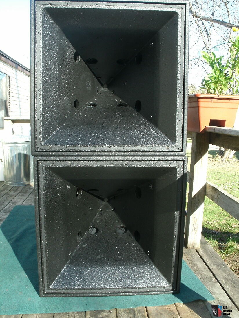
Adding ports is easy if you've planned it out in advance what you're going to do. I do recommend using a separate woofer mounting pad of ply or MDF, etc. that can be later switch out with larger one(s) custom made for purpose. This would allow you to upgrade to four 15" woofers/horn, especially if you are going to elongate the ports later to double their effective area (going from 2 ports/woofer to one port/woofer when doubling the number of 15" woofers on the horn--the long ports on top and bottom horn walls for the SH-96 shown here servicing one 15" woofer per port):

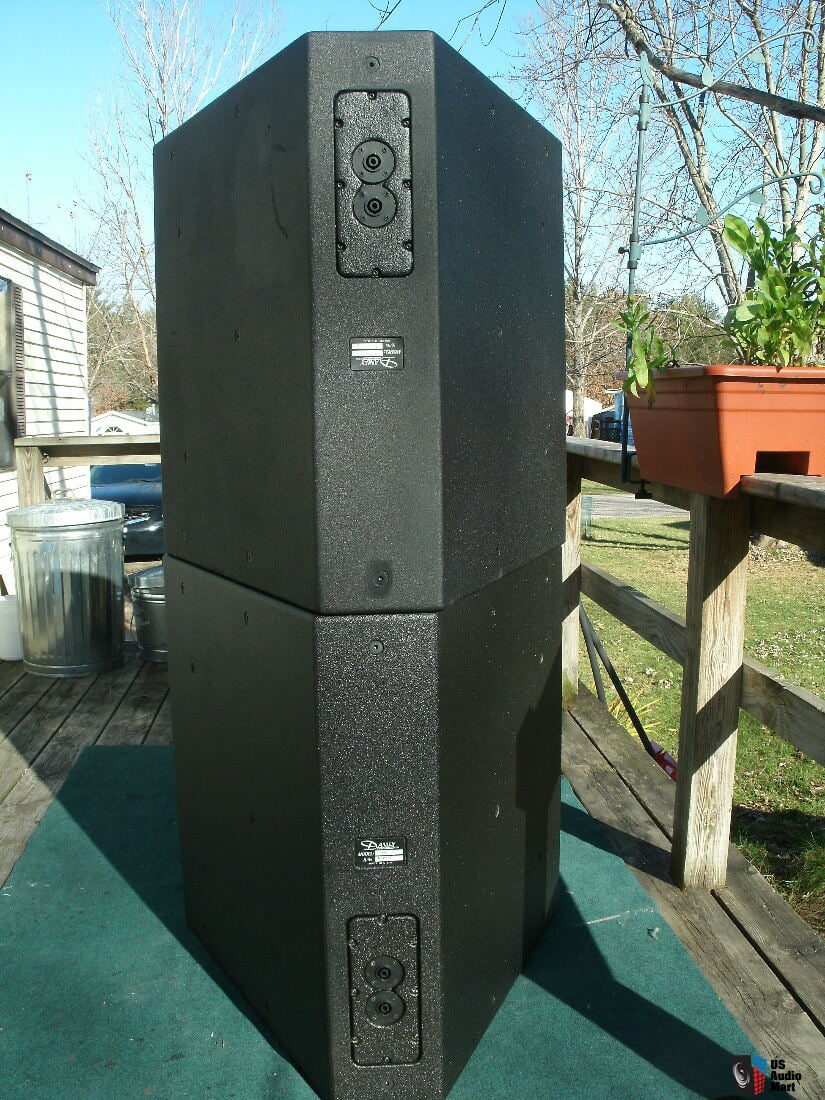
The reverse side of the SH-96 showing the woofer mounting surfaces:

Using through bolts with countersunk heads to clamp to the horn from the inside surface of the horn (as Danley does it) seems to be the most productive way to clamp to horn tightly. This also facilitates drilling the off-axis ports so that the woofer mounting pad doesn't shift around. A picture of SH-50s showing the countersunk through bolts that are used to hold the box to the horn (side wall surfaces in this picture) and the woofers to the horn (top and bottom horn walls in this picture), thus stiffening the entire structure and cutting down on resonances:
and the reverse side showing the threaded countersunk nuts for the through bolts on the side walls of the box:
Chris
Adding ports is easy if you've planned it out in advance what you're going to do. I do recommend using a separate woofer mounting pad of ply or MDF, etc. that can be later switch out with larger one(s) custom made for purpose. This would allow you to upgrade to four 15" woofers/horn, especially if you are going to elongate the ports later to double their effective area (going from 2 ports/woofer to one port/woofer when doubling the number of 15" woofers on the horn--the long ports on top and bottom horn walls for the SH-96 shown here servicing one 15" woofer per port):
The reverse side of the SH-96 showing the woofer mounting surfaces:
Using through bolts with countersunk heads to clamp to the horn from the inside surface of the horn (as Danley does it) seems to be the most productive way to clamp to horn tightly. This also facilitates drilling the off-axis ports so that the woofer mounting pad doesn't shift around. A picture of SH-50s showing the countersunk through bolts that are used to hold the box to the horn (side wall surfaces in this picture) and the woofers to the horn (top and bottom horn walls in this picture), thus stiffening the entire structure and cutting down on resonances:
and the reverse side showing the threaded countersunk nuts for the through bolts on the side walls of the box:
Chris
Last edited:
A little misleading, calling them this, don't you think?off-axis ports,
It's not difficult to add off-axis ports, especially if you have some way to clamp the horn for hole-saw drilling. A drill press with a makeshift fixture would work.
Adding ports is easy if you've planned it out in advance what you're going to do. I do recommend using a separate woofer mounting pad of ply or MDF, etc. that can be later switch out with larger one(s) custom made for purpose. This would allow you to upgrade to four 15" woofers/horn, especially if you are going to elongate the ports later to double their effective area (going from 2 ports/woofer to one port/woofer when doubling the number of 15" woofers on the horn--the long ports on top and bottom horn walls for the SH-96 shown here servicing one 15" woofer per port):
The reverse side of the SH-96 showing the woofer mounting surfaces:
Using through bolts with countersunk heads to clamp to the horn from the inside surface of the horn (as Danley does it) seems to be the most productive way to clamp to horn tightly. This also facilitates drilling the off-axis ports so that the woofer mounting pad doesn't shift around. A picture of SH-50s showing the countersunk through bolts that are used to hold the box to the horn (side wall surfaces in this picture) and the woofers to the horn (top and bottom horn walls in this picture), thus stiffening the entire structure and cutting down on resonances:
and the reverse side showing the threaded countersunk nuts for the through bolts on the side walls of the box:
Chris
Ok thanks! This is going more into the construction aspect of it all, something I'm looking into more and more know.
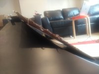
1. You dont need a chamber between the woofer and the off axis port?Just mount the driver directly to the horn (or in this case, the mounting pad). Does it matter when distance the off axis port will have? Or can I just model this in both cases? It seems like my horn isnt completely straight, so mounting a big woofer will create a gap of around 1-1,5" at its biggest distance. I includded a picture of a carton square (18" sides) on the side of the horn, you can clearly see the gap. I'm pretty sure I can sturdly fill in this gap, but it will create a chamber. Can I just guess how big this gonna be, or should I measure/calculate this before modelling/constructing?
Also, to ensure that the horn doesnt vibrate due to the woofers I would like to use 1" or even thicker MDF for woofer pad. Just model it like this, or should I keep the port shorter?
2. Does Danley also use a 10:1 ratio? Doesnt look like it?
3. How much space of a horn would you dare to take in with ports? You used 1" wide ports, and elongated them, but my horn is a bit bigger. You think I can get away with 2x 1,5 or even 2" slots elongated on each side?
4. When using woofer pads, do I still need to strengthen the walls of the horn? The woofers will be attached to the pad, and the pad can be mounted (with the screws you mentioned) to the sides of the box, instead of securing it all to the horn.. I can use extra bracing to ensure the vibrations of the woofers influence the walls of the horn as less as possible.
Or would it still be smarter to reinforce the walls of the horn (where it is not covered by a wooferpad) with some epoxy/other material to make sure it doesnt vibrate with the generated backchamber vibrations and pressure?
5. It looks like Danley doesnt place it ports in the center of the woofer. Does this matter? And if so, how much would be an acceptable deviation?
It looks like I will not be able to mount 4x 15" woofers if they are placed in the center of the horn wall. If I can side mount them like in the SH96 I can definitely pull it off. Then I can maybe even pulll of 4x 18" woofers.
Side note, I'm still figuring out the S1/S2/S.. and their aspect (conical, ..) etc, but when I do I ll start modelling. I already have a few drivers in my sight I want to try to model.
Attachments
No, you don't.1. You don't need a chamber between the woofer and the off axis port?
Which distance?Does it matter when distance the off axis port will have?
Thinner at the port entrance to the horn would be better.Also, to ensure that the horn doesn't vibrate due to the woofers I would like to use 1" or even thicker MDF for woofer pad. Just model it like this, or should I keep the port shorter?
Close--about 7:1 on the SH-50.2. Does Danley also use a 10:1 ratio? Doesn't look like it?
My off-axis ports use a diameter of 2.6 inches each.3. How much space of a horn would you dare to take in with ports? You used 1" wide ports, and elongated them, but my horn is a bit bigger.
The areas not supported by the woofer's mounting surface need to be reinforced. That means it would be advantageous to use a horn with reinforced horn walls that the woofers are not mounted on.4. When using woofer pads, do I still need to strengthen the walls of the horn?...Or would it still be smarter to reinforce the walls of the horn (where it is not covered by a wooferpad) with some epoxy/other material to make sure it doesnt vibrate with the generated backchamber vibrations and pressure?
Yes, I think it does. I've talked about this in the full-range MEH kit thread.5. It looks like Danley doesn't place it ports in the center of the woofer. Does this matter?
Chris
These are the multiple entry ports, who's purpose is to put sound on-axis? and if they cause interference it will show on-axis?My off-axis ports
I recommend some light reading, Allen: http://www.danleysoundlabs.com/wp-content/uploads/2012/01/The-Tapped-Horn.pdf
No, you don't.
Which distance?
Thinner at the port entrance to the horn would be better.
Close--about 7:1 on the SH-50.
Ok, so if I'm planning on using 4 woofers, using a smaller ratio might be benificiary to not take in too much place with the port openings into the horn.
My off-axis ports use a diameter of 2.6 inches each.
2,6" wide then? Because otherwise you wouldnt get the 10:1 compression ratio right?
The areas not supported by the woofer's mounting surface need to be reinforced. That means it would be advantageous to use a horn with reinforced horn walls that the woofers are not mounted on.
Will do.
Yes, I think it does. I've talked about this in the full-range MEH kit thread.
Chris
Sorry I was incorrect about the length thing between woofer and horn, so nevermind that. But if you say, keep it as short as possible, how short? Because the horn curves too early there will be a gap of about 1-2cm (although maybe less, got to remeasure tomorrow) between the mounting pad and the horn. I can fill this gap up on the sides, but it will still be an added "thickness" of the off-axis port. In any case, I'll stay with 0,75" MDF then, as to not increase this even further.
Reading through it now, and will read through it tomorrow some more. Already some interesting things, also pertaining to my other questions.
"2. The off-axis ports in my prototype are actually 2.5 cm deep (1"), but I'd recommend they be much shallower. You can taper the woofer mounting pads in the off-axis port areas to thin them down to the horn's ABS material thickness, starting about 2.5 cm or more away from the through hole."
=> using this I can ensure that I keep a shallow port, even with the little gap I might have. I was already planning in rounding them, but not to this extent.
Sadly I dont readily find the discussion about the port position. Will have to look for it tomorrow.
Also, how far should I take the wooer modelling? I know the response you finally got wasnt what you modeled, but why then do it? What do I look at? Is it a good way to compare woofers? Or? And if I cant go by modellling, then how do I know it is a good fit? What T/S parameters would you recommend I focus on for the best low-end performance (down to 60-100hz).
Modeling in Hornresp will tell you the first notch frequency of your off-axis port locations (which is a vital piece of information) but not the performance of size of the ports. It won't tell you the on-axis SPL of your woofers but it will tell you the relative performance of woofers in a qualitative way. You'll need to build and test them to see the real frequency and phase responses. That's where a DSP crossover comes in handy: to EQ the output flat below the first notch frequency and to attenuate the response above the first notch frequency.
In the K-402-MEH, that means setting two to three attenuating PEQ filters above the first notch frequency of ~650 Hz: one peak at 1320 Hz and another at ~2600 Hz, and perhaps a third notch centered at 3400 Hz. The woofers and 2" compression driver will couple and act as one driver in their crossover interference band. The other frequency bands will behave like a regular horn-loaded loudspeaker. You can use a first order crossover filter between the woofers and compression driver, or you can simply set the woofer channel delay to around 0.5 ms (corresponding to 90 degrees of phase lag to approximate a first order crossover) and use no crossover filters. The results will perform almost identically in terms of phase and on-axis SPL response in my experience (surprisingly). This is most likely true due to the coupling of the compression driver output to the woofer output. This is a phenomenon that is largely absent from other horn-loaded loudspeakers, i.e., the coupling that takes place between drivers in an MEH.
I would not use any higher order crossover filters than first order, only attenuating PEQs to bring down SPL response peaks. The resulting SPL and phase response of the MEH will get your attention when you play good music recordings having a high degree of phase fidelity (i.e., acoustic music performances recorded with all musicians playing at the same time in the same open venue).
Chris
Last edited:
Modeling in Hornresp will tell you the first notch frequency of your off-axis port locations (which is a vital piece of information) but not the performance of size of the ports. It won't tell you the on-axis SPL of your woofers but it will tell you the relative performance of woofers in a qualitative way.
Chris
" that means setting two to three attenuating PEQ filters above the first notch frequency of ~650 Hz: one peak at 1320 Hz and another at ~2600 Hz, and perhaps a third notch centered at 3400 Hz."
Can you show me the graph showing you those 3 notches? So I can figure out myself what the notches will be in mine. And where do you apply the 3 PEQs? On the input? Or only on the HF driver?
but it will tell you the relative performance of woofers in a qualitative way.
As in that it is a way to compare woofers? So if a woofers performs better in the modelling, it should also work better in the MEH? You wont know how it wil perform if you dont measure it, but it can help me pick the one that is gonna be the best one?
Or what do you mean by qualitative?
- Home
- Loudspeakers
- Multi-Way
- Amount of hornloading in a Synergy horn