With the affordability of electronic crossovers and multi amp channels these days there is less need for passive crossovers - which is a good thing. This is especially true at the first crossover point, where passive components would be large and expensive. However, in a three way, tri-amping does increase complexity, and depending only on an electronic hi pass, it could put a tweeter in danger. If any low frequency information got to the tweeter it would burn out, so some people still like passive components for the mid to high crossover point.
Crossover design is something I have limited experience with, and most of that is by ear measurement only. But I have built some speakers that sound good!
I will continue to experiment with passive components, and continue to read more about it, but what I have read so far tends to confuse me. Some speaker builders with good reputation will say that the crossover is the most important part of the speaker system. Recently I read from one (can't remember which) that any variation in drivers, driver placement, or cabinet design requires a different crossover. But in a white paper from Fried Speakers, also a well respected mfr of transmission line designs, they claimed that first order networks are by far the best, if drivers can be found that can work 3 octaves passed the desired x-over point because of the 6db roll off. I tend to agree with this, as I have personally realized how adding extra components will increase 'insertion loss'. Components eat up power. Besides this, a first order is cheaper and easier.
I'd be interested to hear any input you folks have.
JT

For what its worth re; tweeter damage.
I've been thinking of a tri-amped setup where I use a 10 watt class amp (JLH 1969). This unit is normally a single rail PSU and so has an output cap' which can now be reduced in size from a 2,500 uFs electro's to only a few uFs of high quality plastic cap' and if the value is chosen appropriately can form one pole of the high pass filter. Of course if your going 1st order it can constitute the complete filter...
You do get a few nice trade off by going active.
Cheers, Jonathan
The myth persists that a simple 1st order crossover (inductor on woofer, capacitor on tweeter) are the best crossover design. The fact is, a true first order crossover is much more complicated and not without significant drawbacks.
Thiel CS2 2 loudspeaker First-Order Filters | Stereophile.com
Thiel CS2 2 loudspeaker First-Order Filters | Stereophile.com
This might be commercial interest because they use first order. Anyway, the expense of capable drivers makes an active system even more worthwhile.But in a white paper from Fried Speakers, also a well respected mfr of transmission line designs, they claimed that first order networks are by far the best, if drivers can be found that can work 3 octaves passed the desired x-over point because of the 6db roll off.
With the affordability of electronic crossovers and multi amp channels these days there is less need for passive crossovers - which is a good thing.
Not automatically it isn't. Active has advantages, but it isn't a panacea and has its own issues which do not suit everyone.
Crossover design is something I have limited experience with, and most of that is by ear measurement only.
There is no such thing as ear measurement only.
I will continue to experiment with passive components, and continue to read more about it, but what I have read so far tends to confuse me. Some speaker builders with good reputation will say that the crossover is the most important part of the speaker system.
Assuming you are using reasonable quality drive units, then yes, in a sense it is, since it determines the overall frequency, phase & impedance responses.
Recently I read from one (can't remember which) that any variation in drivers, driver placement, or cabinet design requires a different crossover.
Correct.
But in a white paper from Fried Speakers, also a well respected mfr of transmission line designs, they claimed that first order networks are by far the best, if drivers can be found that can work 3 octaves passed the desired x-over point because of the 6db roll off.
There is no such thing as 'best' sans definitions, and even then, not everyone is obliged to agree; it isn't a case of 2 + 2 = 4. For example, the word 'if' is a fairly significant caveat there, and it's certainly not the only one. 1st order can be fine if you have drive units with a very wide, flat BW (not easy, and even less easy to do with high qualities elsewhere) and similar polar responses through the relevant transition bands to avoid shifts in tonal behaviour &c. If you don't -well, you can be in for a merry time.
")
I tend to agree with this, as I have personally realized how adding extra components will increase 'insertion loss'. Components eat up power.
Resistors certainly do for obvious reasons.
High DCR inductors also do (so use a low DCR one if this is a problem; sometimes the resistance may be used as a part of the transfer function). There are very few power losses in most film / film & foil caps. Passive filters however are by definition subtractive i.e. lossy; you can't boost or add, only take. Besides this, a first order is cheaper and easier.
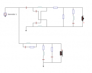
Usually the opposite is the case; the slow 6dB/octave rolloffs tend to require additional components. Extra protection is often necessary; some kind of impedance compensation is also often required to ensure the rolloff behaviour remains consistent, and likewise some response shaping to prevent issues in the nominal stopband affecting the response. Which is before you get to the question of aligning the drivers; if you can't do so physically, then you have to do so electrically. For example, the attached is a 1st order design. 18 components needed. LR4 with the same drivers & a slightly lower crossover frequency required 8.
Attachments
Last edited:
I also prefer an first order cr, and a recent one i made for a 2 way WAW system has 2 inductors, 5 resistors and 3 caps in it per channel. And you need wide band drivers, the cr goes arround 200Hz, but the sub can go untill 1200Hz and the top (FR driver) goes down to 40Hz. That extra space in bandwith is needed for the slow slope.
But the sound of a good 1st order is way better than other orders, it's more coherent and lively than steeper filters in my opinion.
But the sound of a good 1st order is way better than other orders, it's more coherent and lively than steeper filters in my opinion.
For what its worth re; tweeter damage.
I've been thinking of a tri-amped setup where I use a 10 watt class amp (JLH 1969). This unit is normally a single rail PSU and so has an output cap' which can now be reduced in size from a 2,500 uFs electro's to only a few uFs of high quality plastic cap' and if the value is chosen appropriately can form one pole of the high pass filter. Of course if your going 1st order it can constitute the complete filter...
You do get a few nice trade off by going active.
Cheers, Jonathan
I always feel a little pain when I hear people talk about how the output AC coupling cap "protects" the driver (e.g. tweeter) against tweeter "damage". I assume "damage" means what happens if/when the amplifier faults and the output goes to one rail or the other. Yes, indeed, that could destroy the driver in short order. But are you really getting the "protection" that you think you are?
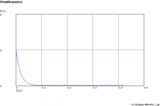
The problem with this idea of "protection" is that a DC step response fed to a first order filter results in a large spike at the filter output before it settles back to zero. A step response is exactly what happens when the amp faults to a rail. The output does return to 0, but the driver does see a good portion of, if not the full, rail voltage at the peak of the response, even if just for a short moment in time. This is not quite the vaulted "DC protection" that it's often cracked up to be. It's only blocking 100% for a steady-state condition in which DC is present, but this is not true for transient condition. In the instant of the fault there is exactly that, a voltage transient, namely a step in the voltage fed to the output filter.
What I feel that many (most?) people do not realize is that for a class-A amp like the JLH design, First Watt stuff, etc. every time the amp is switched on there is the exact same step of the voltage across the cap, from 0V (when the amp is switched off) to half the rail voltage when the PS fires up and the output devices dutifully assume 1/2*Vcc. The AC coupling cap is going to react to the rapid change and pass a voltage spike on to the driver until it finally settles back down to 0V on the output side. This is simply how a first order RC filter works.
I have attached the 0-->1 step response of a first order filter of 2200uF into 8 Ohms for your enjoyment. Replace "1" with half of whatever rail voltage you are using and you can see the problem.
A clever solution, and one which I believe NP uses, is to leave the amp powered up all the time so the AC coupling cap is always charged up to the midpoint voltage and the output remains at zero. You could also rig up a time delay relay that will connect the output to a power resistor equal to the nominal load impedance until the output has stabilized if you don't like your class-A heater to run 24/7.
Attachments
Scott
I was looking at the cross over that you designed and was wondering what was the purpose of the two inductors in series on both the + & - with the parallel caps crossing over the way they do? I can't say I've ever seen that before. It's interesting.
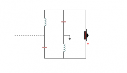
It's an all pass filter, aka a ladder delay circuit. On a flat baffle, a typical dome tweeter has its acoustic centre physically further forward than that of the midbass [in this case]. This is just a matter of physical size & construction, but it does mean the output of the latter is delayed in relative terms to that of the tweeter. Higher order filters (generally 3rd order acoustical slopes or higher) are less affected, but for 1st and 2nd order acoustical slopes, some kind of compensation is almost always necessary. You can do that physically, either with a stepped front baffle e.g. Duntech / Dunlavy et al (Troels Gravesen does this for his many LR2 designs also), a tilted front baffle like Thiele & others use, a waveguide for the tweeter that moves it sufficiently far back (this is assuming you also want the controlled directivity) or you can do it electrically. There are other ways of drawing it of course e.g. the attached. Dynaudio use all pass circuits a fair bit. They can all work well enough if properly implemented, so you do what best suits a given set of requirements.
Attachments
Last edited:
I haven't built a passive system since 01/02 and seldom put anything in the HF circuit to protect the driver. In all the dozens of domestic and PA systems, I've never once damaged a tweeter. It's not luck, it's system design.However, in a three way, tri-amping does increase complexity, and depending only on an electronic hi pass, it could put a tweeter in danger.
Edit: I hadn't read Charlie's post #14 when I posted. It's great, so I'll just ditto it re series caps.
Last edited:
But are you really getting the "protection" that you think you are?
IMO, yes.
Continuous power (heat) kills speakers, and little is required to kill a 1" dome tweeter. If you're lucky, you'll have seconds to turn the amp off before the voice coil on a dome tweeter cooks.
A cap to block the DC component will still allow a large transient, of course, but will block the signal that would normally destroy the voice coil.
Chris
Exactly. That's why I wrote (quoted with my emphasis in blue):
It's only blocking 100% for a steady-state condition in which DC is present, but this is not true for transient condition. In the instant of the fault there is exactly that, a voltage transient, namely a step in the voltage fed to the output filter.
It will prevent the fault condition from continuously being applied to the tweeter. That's good! But I expect the tweeters receives quite a blow with the initial spike, and with a class-A amp you get a 1/2*Vcc spike every time you turn on the amp. I can't see how that is good for the driver...
I don't own any class-A equipment, or "fragile" tweeters. Maybe in practice it's not really a problem? Can someone comment on this?
Yes. Used delayed turn on, and output turn off before power down. Better yet, sequence the entire system to turn on/off without thumps. I've been doing this for at least 3 decades (home and PA), and it's a darn sight easier now with devices like the Arduino, than having to program an 8051 in assembler or FORTRAN/BASIC etc.I don't own any class-A equipment, or "fragile" tweeters. Maybe in practice it's not really a problem? Can someone comment on this?
- Status
- This old topic is closed. If you want to reopen this topic, contact a moderator using the "Report Post" button.
- Home
- Loudspeakers
- Multi-Way
- Passive Crossovers ...