Could use some help from those in the know about this...
How do you measure the reflections that bounce back into a horn's throat ?
I'd like to determine the frequency of the reflections, and their arrival time at the throat vs the original signal.
What measurements .... impulse, spectrogram, etc, would you use?
Any examples of how to do this, in a quasi anechoic testing environment, would be greatly appreciated...
Many Thanks in advance! mark
To be honest, "I" don't measure them -- at least directly. Some of the reflections can be calculated based on the resonances of the horn: mainly the depth of the axis. Look in the linked article where it discusses pink noise for freq. responses. Beyond the fundamental resonance, I have no idea how other reflections are measured. You can look up "HOM" in a search and find more about it.
Factors Affecting Sonic Quality of Mid & HF Horns & Waveguides
Factors Affecting Sonic Quality of Mid & HF Horns & Waveguides
How do you measure the reflections that bounce back into a horn's throat ?
They may show up in the impedance curve (for the frequency), and in the step
response (for the time delay).
Last edited:
Hello,
Reflection, think resonance and stored energy.
Impedance plots show resonance.
Waterfall plots show resonance and stored energy.
for a start read this
Frequency Response: Waterfalls
Thanks DT
Reflection, think resonance and stored energy.
Impedance plots show resonance.
Waterfall plots show resonance and stored energy.
for a start read this
Frequency Response: Waterfalls
Thanks DT
Fulcrum Acoustic do this, they extract horn reflection and other anomalies from their speakers and implement preconditioning FIR filters to cancel them out.
Don't know the specifics but you might find some usefull nuggets from David Gunnes papers, see these
https://www.fulcrum-acoustic.com/as...dspeaker-transient-response-with-dsp-2005.pdf
https://www.fulcrum-acoustic.com/as...ogram-loudspeaker-transient-response-2005.pdf
More Whitepapers | Fulcrum Acoustic
Last edited:
I think you can see them in impulse spectrograms that HornResp can generate. Do a horn sim, especially one without a mouth termination, and you will see a series of weak impulses after the first in the impulse/spectrogram. What else could they be?
So yes, mouth reflections will be in the spectrogram but so will everything else...The mouth reflections will be what appears at the delay corresponding to twice the horn depth.
Trouble is REW's spectrograms don't look a bit like HR's impulse spectrograms
So yes, mouth reflections will be in the spectrogram but so will everything else...The mouth reflections will be what appears at the delay corresponding to twice the horn depth.
Trouble is REW's spectrograms don't look a bit like HR's impulse spectrograms
Thank you everyone,
and tmuikku.....yes, Dave G's papers and patents are exactly what I'm trying to duplicate.
I've been studying them for over a year with no mental breakthoughs till recently. I think I've figured out how to do the dsp if I can precisely identify the reflections ..
and tmuikku.....yes, Dave G's papers and patents are exactly what I'm trying to duplicate.
I've been studying them for over a year with no mental breakthoughs till recently. I think I've figured out how to do the dsp if I can precisely identify the reflections ..
that is the thing, isn't it? Perhaps an adaptive filter can be done. Digital communications has problems because there are multiple paths from Tx to Rx so algorithms have been developed to adaptively cancel the delayed data. In this scenario, you train the filter based on a known signal (e.g a square wave) to best reproduce that signal at the mouth of the horn. Of course manual adaptation would be a bear. If you could automate it, you would have something.
Yeah, its a bit frustrating for DIYer to know that it is not possible to achieve very best sound unless these anomalies are addressed by DSP. I mean, every CD and horn have these fixable "problems", but it takes a lot (a lot lot) effort to tackle the measurements and filter design.. at least I'm frustrated ") If only had enough green to buy fulcrum speakers, or hire mr. Gunnes to generate filters for my DIY speakers
If only had enough green to buy fulcrum speakers, or hire mr. Gunnes to generate filters for my DIY speakers
I remember reading Gunnes comment somewhere that exact measurements (identification of the reflections) is mandatory, otherwise the precondition filter won't do any good. Anyway, Good luck!
If only had enough green to buy fulcrum speakers, or hire mr. Gunnes to generate filters for my DIY speakers I remember reading Gunnes comment somewhere that exact measurements (identification of the reflections) is mandatory, otherwise the precondition filter won't do any good. Anyway, Good luck!
Last edited:
that is the thing, isn't it? Perhaps an adaptive filter can be done. Digital communications has problems because there are multiple paths from Tx to Rx so algorithms have been developed to adaptively cancel the delayed data. In this scenario, you train the filter based on a known signal (e.g a square wave) to best reproduce that signal at the mouth of the horn. Of course manual adaptation would be a bear. If you could automate it, you would have something.
You're over my head ! Unless maybe the adaptive filter is some kind of automatically applied impulse-inversion, convoluting thing-a-ma-bob
You will find lots of papers on the communication delay eliminating algorithms. I looked some papers a while go but my brain starts farting, too much to diggest You'll need microsecond precision with horns/compresion drivers though, don't know if these communication algorithms are up for it. Also, they seem to be mostly for electronic paths. Maybe there are some papers that consider acoustic feedback (speech PA systems in lecture halls or something like that).
You'll need microsecond precision with horns/compresion drivers though, don't know if these communication algorithms are up for it. Also, they seem to be mostly for electronic paths. Maybe there are some papers that consider acoustic feedback (speech PA systems in lecture halls or something like that).
Last edited:
Yeah, its a bit frustrating for DIYer to know that it is not possible to achieve very best sound unless these anomalies are addressed by DSP. I mean, every CD and horn have these fixable "problems", but it takes a lot (a lot lot) effort to tackle the measurements and filter design.. at least I'm frustrated
I remember reading Gunnes comment somewhere that exact measurements (identification of the reflections) is mandatory, otherwise the precondition filter won't do any good. Anyway, Good luck!
I hear you!
I'm really interested in this because a number of prosound guys say that the fulcrum boxes are some of the rare boxes they prefer to equivalent output/coverage synergies.
It is - with a difference. In FIR, you specify tap weights to achieve a frequency/phase response. In this adaptive filter you change the tap weights to achieve a square wave out of the horn, e.g., for a square wave into.
Adaptive filter means nudging the tap weights in a direction to minimize an error function on successive measurements. Reflections, even mouth reflections, are delayed copies of the "signal" so it stands to reason if you had a tapped delay line that spanned 2x the time length of the horn you should be able to null the reflection(s). If it were just a single reflection it would be easy but as you see in the papers its not that simple. Plus adapting for square wave out for square wave in corrects more than just mouth reflections.
wiki says it better than me but this is heavy stuff if you haven't been exposed to it before:
Adaptive filter - Wikipedia
Alright, I'm trying to interpret the Gunnes papers.
I think adaptive filters won't work as such, since the different "two-port" subsystems of a loudspeaker must be addressed separately.
Quote from the https://www.fulcrum-acoustic.com/as...dspeaker-transient-response-with-dsp-2005.pdf
"Loudspeakers, in general, are not two port systems, because their transfer functions vary with both direction and distance. A preconditioning filter may improve the response in one direction, while making it worse in another.
However, many of the mechanisms that are used to construct a loudspeaker are two-port in nature. As a result, a preconditioning filter designed to address a specific subsystem may improve the performance of the
loudspeaker in all directions, or at least over the loudspeaker’s intended coverage pattern. Four specific loudspeaker mechanisms will be described, all of which satisfy the requirement of being largely correctable, two-port subsystems. "
From the paper, these four two-port sub systems are
1. Compression Driver Phase Plugs
2. Horn Resonance
3. Cone Resonance
4. Crossover Phase Linearity
This thread is about the number 2.
Another quote from the same paper:
"The preceding discussion established that loudspeakers exhibit many imperfect behaviors which are not good candidates for corrective filtering. Furthermore, each of these behaviors affects the loudspeaker’s measured transfer function. So, a single transfer function measurement is not an optimum reference from which to develop a correction filter.
It is better to develop corrective filters by targeting specific subsystems which are LTI two-port subsystems. Filters to correct each of these subsystems can be developed from their measurable dimensions and parameters, or by painstakingly separating the response of the subsystem from the response of the overall system. "
Alright, so it seems one can use mathematics to develop such filter for horn reflections. Maybe start studying stuff mentioned in the paper such as "characteristic
acoustical impedance" and "reflection coefficient of a transmission line termination" and see whats there to learn. There must be examples on the web how to use these in a mathematical function
My simple uneducated guess is that reflected signal from a discontinuity (in case of a horn) is a low passed and delayed signal of the original. Delay can be calculated from the horn dimensions, low pass, I don't know.
If you want to measure the reflection, I guess its better not to use compression driver as signal source (it is another sub system) but something else. Also, maybe use simple pipe or conical horn made out of paper with only one discontinuity (mouth) to get started. Try to get the math and measurement match.
Hopefully my post contains enough inspiration ( or false information ) so that some discussion emerges. I'd really like to implement some of these Gunnes stuff in DIY build
Last edited:
Alright, mucho here https://www.grc.com/acoustics/an-introduction-to-horn-theory.pdf and propably a lot more easily found.
Its been a while since I read the Gunness papers and longer still (decades) since I took a graduate course in "Learning and Adaptive Machines" so I am no expert, but I have had a taste.
All those things you brought up is why Gunness filtering is pretty special, non-trivial to do. If you model the output of a horn as a primary output followed by a series of delayed reflections then it looks like so form of adaptive filtering might work, and it might, but the question is how well.
The problem is that the mouth delay model is overly simplistic. What one needs to do is develop a more complete model of the horn system, e.g. as a number of filters with delay whose outputs are summed at the horn mouth. estimate the filter and delay parameters from measurements and then use the estimates to define a set of filters that correct the individual subsystems or the final result. Wait a minute - isn't that essentially what Gunness does, less the adaptation?
I would only try this on a good constant directivity horn...
Mark,
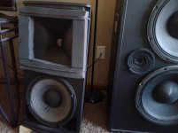
I've been on a long search for a low reflection horn. I had a close friend who knew a lot. There are some things to stay away from, such as parallel walls (diffraction slots), corners (good luck with non circular), and edges. Look for smooth paths, not a series of straight lines that "angle" away. I had a big ev hp 640 that added a "live" reverb sound to everything, fine for pa, not for reproduction.
Waveguides seem to be an answer, and they don't narrow dispersion the higher in frequency you go.
I add that I'd like the mouth to slowly bend to the baffle.
Shoter horns sound better thgan deeper, but it depends where you want to cross at. Currently 12" 2-way 1,200hz crossing works for my varied tastes (movies to dianna krall to halsey/ariana pop). Sure my morel 2-way is far more detailed, but I'd like mid bass further than 7' from my speaker and i occasionally turn it up loud.
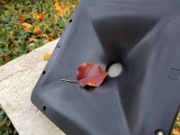
I have luck with my current pt waveguide, but would like to try the newer one. Mine has a bubble in the throat, but other wise no complaints.
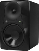
For clean horns, look to the smaller monitors such as behringer truth or mackie mr824.
I've been on a long search for a low reflection horn. I had a close friend who knew a lot. There are some things to stay away from, such as parallel walls (diffraction slots), corners (good luck with non circular), and edges. Look for smooth paths, not a series of straight lines that "angle" away. I had a big ev hp 640 that added a "live" reverb sound to everything, fine for pa, not for reproduction.
Waveguides seem to be an answer, and they don't narrow dispersion the higher in frequency you go.
I add that I'd like the mouth to slowly bend to the baffle.
Shoter horns sound better thgan deeper, but it depends where you want to cross at. Currently 12" 2-way 1,200hz crossing works for my varied tastes (movies to dianna krall to halsey/ariana pop). Sure my morel 2-way is far more detailed, but I'd like mid bass further than 7' from my speaker and i occasionally turn it up loud.
I have luck with my current pt waveguide, but would like to try the newer one. Mine has a bubble in the throat, but other wise no complaints.
For clean horns, look to the smaller monitors such as behringer truth or mackie mr824.
Attachments
Its been a while since I read the Gunness papers and longer still (decades) since I took a graduate course in "Learning and Adaptive Machines" so I am no expert, but I have had a taste.
All those things you brought up is why Gunness filtering is pretty special, non-trivial to do. If you model the output of a horn as a primary output followed by a series of delayed reflections then it looks like so form of adaptive filtering might work, and it might, but the question is how well.
The problem is that the mouth delay model is overly simplistic. What one needs to do is develop a more complete model of the horn system, e.g. as a number of filters with delay whose outputs are summed at the horn mouth. estimate the filter and delay parameters from measurements and then use the estimates to define a set of filters that correct the individual subsystems or the final result. Wait a minute - isn't that essentially what Gunness does, less the adaptation?
I would only try this on a good constant directivity horn...
Ah yes, oversimplification is all I can do and understand, didn't even think about what is the goal until read your post: "...
outputs are summed at the horn mouth.".
The mouth reflection has to come back to the mouth again to be audible after bouncing around in the horn, throat, and driver, not a simple delayed copy of the original anymore. Aha moment, feels good to learn at least something
What kind of setup is needed to measure the reflected signal? Twenty different measurements at different angles, sum together,, subtract original? Ha, im way over my head
Speculating from this video YouTube maybe they do it like this: measure (without horn) and fix the compression driver transient response first. Then attach the horn, measure near throat and fix that. Perhaps no mouth reflection correction at all
Anyhow, how to measure?
Woofer cones are used as kick drum mics in studio. So, could one measure the throat reflection hitting the compression driver from the driver terminals, using the driver it self as a measurement device? Then absorb the throat reflection at the driver diaphram with precondition filter. Like they do active noise cancellation.
Hi all, thanks for the continued posts.
@ tmuikku, Yes, item #2. Horn Resonance is what I'm trying to measure.
I had the thought to make a horn with abrupt termination to give me a reflection to look for.
I've been measuring a XT1464 (and bms 4594he)...maybe it's too "reflection free" for a novice who doesn't know what to look for.
But I also like your suggestion to start at the root subsystem, with the driver alone without the horn, and then compare with the horn.
I watched the fulcrum youtubes before..wish I could get something out of the one on FIR...
@nc535, maybe you can answer a question I've had for some time about FIR...you seem well versed here...
Say I measure the driver alone without a horn, and build a FIR file composed of minimum phase EQ's to flatten magnitude and phase.
Then I put the driver on the horn and measure with the previous FIR file running, and build a second FIR for horn correction.
Can I then combine the two FIR files into one file, and if so may I ask you to point me to how?
Or maybe, I should not use FIR for the first step, the driver alone, but use the same EQ's in an IIR 'preconditioning' implementation.
That is the idea I've had for handling reflections if I can identify them, nulling them with delayed reversed polarity IIR EQs.
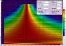
@ norman, thx for the good info. As said above, I'm using the 4594he on a XT1464 (and on a rcf hf950). I use those with different 12" implementations depending on SPL needs, but all implementations crossover at 650Hz.
@ all, I posted the following spectro on a current thread about the 4594....it's a single point on-axis tuning i made the other day after I got frustrated trying to pinpoint reflections...
had to accomplish something/anything that looked good or showed promise lol
@ tmuikku, Yes, item #2. Horn Resonance is what I'm trying to measure.
I had the thought to make a horn with abrupt termination to give me a reflection to look for.
I've been measuring a XT1464 (and bms 4594he)...maybe it's too "reflection free" for a novice who doesn't know what to look for.
But I also like your suggestion to start at the root subsystem, with the driver alone without the horn, and then compare with the horn.
I watched the fulcrum youtubes before..wish I could get something out of the one on FIR...
@nc535, maybe you can answer a question I've had for some time about FIR...you seem well versed here...
Say I measure the driver alone without a horn, and build a FIR file composed of minimum phase EQ's to flatten magnitude and phase.
Then I put the driver on the horn and measure with the previous FIR file running, and build a second FIR for horn correction.
Can I then combine the two FIR files into one file, and if so may I ask you to point me to how?
Or maybe, I should not use FIR for the first step, the driver alone, but use the same EQ's in an IIR 'preconditioning' implementation.
That is the idea I've had for handling reflections if I can identify them, nulling them with delayed reversed polarity IIR EQs.
@ norman, thx for the good info. As said above, I'm using the 4594he on a XT1464 (and on a rcf hf950). I use those with different 12" implementations depending on SPL needs, but all implementations crossover at 650Hz.
@ all, I posted the following spectro on a current thread about the 4594....it's a single point on-axis tuning i made the other day after I got frustrated trying to pinpoint reflections...
had to accomplish something/anything that looked good or showed promise lol
Attachments
- Status
- This old topic is closed. If you want to reopen this topic, contact a moderator using the "Report Post" button.
- Home
- Loudspeakers
- Multi-Way
- Measuring horn reflections back into the throat