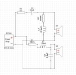
Hello, I've come up with a 2nd order design using XSim (as in the pic) and am wondering if there is anything obviously wrong about this design?
This crossover gave a reasonably flat transfer function. What I'm also not sure though if 10W-rated resistors would work for this 2x25W setup.
Would appreciate any comment! Best wishes, h.
This crossover gave a reasonably flat transfer function. What I'm also not sure though if 10W-rated resistors would work for this 2x25W setup.
Would appreciate any comment! Best wishes, h.
Attachments
What are the actual speakers (part#)? Where did you get your FR and ZMA curves for your XO design? Did you measure with a Mic (FR graph) and some sort of "jig", like DATS (ZMA files)? Or did you trace from Manufacture curve? If so, did you take minimum phase for the each file before simulating?
Also, posting your actual FR graph (with phase included) would greatly assist you getting the best advice possible.
Also, posting your actual FR graph (with phase included) would greatly assist you getting the best advice possible.
what exactly are the resistor values? isn't M a meg? or milli...?
My guess is that R2 and R3 have values of milli-ohms, and are probably the dc resistances of the coils. Just a guess.
Thank you guys! Appreciate your help! Good, if 10 W resistors are acceptable, then I have all the parts ready. Yes, R2 and R3 are 0.65 Ohm. R3 is taken care of by the resistance of L2.
The manufacturers provided all the data files to XSim. I applied the last coat of finish to my speakers yesterday and bought my first soldering iron for final assembly. I guess I'll test my crossover tonight by listening.
The manufacturers provided all the data files to XSim. I applied the last coat of finish to my speakers yesterday and bought my first soldering iron for final assembly. I guess I'll test my crossover tonight by listening.
You can include R3 in L2, right-click and choose "tune" then change the ESR to the 0.65r and you can remove R3. Currently you will have L2 assumed ESR in there as well, so it's being double counted. Shouldn't make a big difference but will bring your low-end up at Fs slightly.
Do the same think with L1 and R2 - you might find you still need some resitance in teh tweeter circuit to get your phase to line up.
Additionally - you could use a "tank" over the L2 in oyur woofer circuit, to surpress some 2-3k difraction - try 0.47r to start. THis can significantly help smooth out the FR in the sensitive 2-3k range - if needed.
Again - we could help even more if we knew the drivers and saw your actual FR graph.
Absolutely. I hope the OP doesn't try to add extra resistors. This is the typical way that some simulators show this.My guess is that R2 and R3 .... are probably the dc resistances of the coils.
I'd like to know the answer to the question bullittstang asked in post #5, unless it is a secret of some sort. Dayton Audio provides data, anyone else in the meantime started doing the same? People usually do not apply baffle step response to the manufacturer curves, traditionally being recorded on an "infinite" baffle, so the crossover design may prove to be in need of further work.
Thanks for the feedback, Lojzek! FRD files were provided by the manufacturers. I've read they are measured and phase delay adjusted, which makes them usable for my setup without tweaking.
I didn't include enclosure response in my crossover design. Interesting. Would baffle step for a ~10" box make things drastically different?
I didn't include enclosure response in my crossover design. Interesting. Would baffle step for a ~10" box make things drastically different?
What manufacturer? I think they or you are confused, as I know of no manufacturer that does that - they all use infinite baffle measurements processes, which mean your baffle would make a difference of 4-6db below about 300Hz.
I’ll ask again - what manufacturer and what drivers with you FR and we can tell you if an adjuster would be warranted.
Unclear why you are so secretive????
I’ll ask again - what manufacturer and what drivers with you FR and we can tell you if an adjuster would be warranted.
Unclear why you are so secretive????
- Status
- This old topic is closed. If you want to reopen this topic, contact a moderator using the "Report Post" button.
- Home
- Loudspeakers
- Multi-Way
- first time passive crossover design/build