Ok, my bad with the terminology.
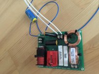
To make sure, here's the reading without a load, and then with the woofer.
That does look like an "I" ( maybe standing for "Infinite".
I'm sure that should be mentioned in the manual.
")
Another Test:
Replace all components to their original positions ( excepting one end of LF-C1 > keep it loose ).
- ( it doesn't matter which end you choose to lift, btw )
Then temporarily remove the 10R resistor ( from the HF portion of the circuit ) and then attach one end of the resistor to the loose end of LF-C1 cap. then attach/solder the free end of the 10R resistor to the point ( on the PCB ) that LF-C1 was originally attached to.
Add drivers to the network and then test again.
If the amp doesn't go into protection now then that means the LF notch ( consisting of L1 + C1 ) is indeed destabilizing the amp up in the UHF region.
That means the notch will need to be redesigned ( by adding a few more components) and will also need to be re-positioned.
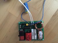
Got a tip I could test this with a homemade "inductor" as well, so went and tested it out.
And it works... See pics below (tested in series both before and after LF_C1 since I was unsure if it would make a difference at that time).
Attachments
Last edited:
Got a tip I could test this with a homemade "inductor" as well, so went and tested it out.
Whats the value of your homemade inductor?
Is your ICE amp actually stable with a 2-ohm load within its pass-band?
XSim says that if the coil value is around 2.4mH then your amp is starting to see a load develop that's less than 2 ohms around 3400hz.
If it's .56mH then your amp is seeing about 1 ohm at 7K ( in a very hiQ notch ).
You should really just add the 10R resistor in place of that mystery coil ( the mystery coil lowers impedance in a very specific but unknown area, while we know the resistor << or lack of >> lowers resistance in the UHF up above 40K ).
IOW, adding the coil ( instead of the resistor ) is not the same test for isolating the problem.
Last edited:
Whats the value of your homemade inductor? Is your ICE amp actually stable with a 2-ohm load within its pass-band?
No idea for both questions
The inductor was just for test.XSim says that if the coil value is around 2.4mH then your amp is starting to see a load develop that's less than 2 ohms around 3400hz.
If it's .56mH then your amp is seeing about 1 ohm at 7K ( in a very hiQ notch ).
You should really just add the 10R resistor in place of that mystery coil ( the mystery coil lowers impedance in a very specific but unknown area, while we know the resistor << or lack of >> lowers resistance in the UHF up above 40K ).
IOW, adding the coil ( instead of the resistor ) is not the same test for isolating the problem.
What does your schematic look like?
I tried to recreate it in XSim, but I might not have gotten it correct. See below.
Anyways, I'm not sure how to move forward here.
Both the XO design by DIY Sound Group and the amp is "kinda faulty", but not really...
Adding a 10R resistor in series with the cap will change the response (judging from XSim), and I don't really want to modify a filter design that should work in the first place.
Attachments
You've laid-out ( within XSim ) the HiPass incorrectly ( as I understand what you previously posted ).
The 10R resistor in series with the 1uF capacitor might just be enough resistance to stabilize the UHF of your amp & save what you currently own ( & you won't know until you actually try it ).
DIYSG designs are beta-tested on typical AVRs.
PS; I'll post my file in a moment
Okay XSim file ( with quick component fix ) has been posted.
Use the "Hold" function to toggle between old values and new values ( I doubt you would hear the difference )
Attachments
Last edited:
You've laid-out ( within XSim ) the HiPass incorrectly ( as I understand what you previously posted ).
The 10R resistor in series with the 1uF capacitor might just be enough resistance to stabilize the UHF of your amp & save what you currently own ( & you won't know until you actually try it ).
DIYSG designs are beta-tested on typical AVRs.
PS; I'll post my file in a moment
Okay XSim file ( with quick component fix ) has been posted.
Use the "Hold" function to toggle between old values and new values ( I doubt you would hear the difference )
Thanks! Much appreciated.Seems a good solution. But I reckon it will have to be one beefy resistor to handle the wattage to the woofer right?
Thanks! Much appreciated.Seems a good solution. But I reckon it will have to be one beefy resistor to handle the wattage to the woofer right?
This is only a viable solution once you've actually tried it and reported back that your amp is stable under common usage.
XSim has a optional graph/window that shows power-dissipation, component-by-component ( just enter into the generator icon, the amount of watts you think you'll use ).
PS; Due to the spectral content that this resistor has to dissipate, I'd be surprised if a 10 watt resistor wasn't actually enough.
Last edited:
This is only a viable solution once you've actually tried it and reported back that your amp is stable under common usage.
XSim has a optional graph/window that shows power-dissipation component-by-component ( just enter the projected watts running, into the generator icon ).
PS; Due to the spectral content that this resistor has to dissipate, I'd be surprised if a 10 watt resistor wan't actually enough.
Nice, about 0.5 watt at 20 kHz
That does look like an "I" ( maybe standing for "Infinite".
I'm sure that should be mentioned in the manual.
Originally an over-range value was indicated by a display of 1999, but that was technically incorrect,
since you could be actually measuring 1999. Then they made the display flash on and off 1999.
Finally, they settled on just displaying the leading 1, to indicate an over-range value.
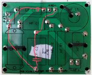
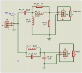
I have helped Defo with this filter on a Norwegian forum. I made a drawing where I overlayed the arrangement drawing of the parts on top of a mirrored picture of the PCB. In this way it is easer to reverse engineer and create a schematic. The overlay is showed in pic1 and the resulting schematic is in pic2.
We can see by following the red line from negative to positive input terminal that there are two capacitors in series. (LF-C1 and LF-C2).
This will effectively short any high frequency signal and I suspect that it is only small variations in components values that makes one of the filters trigger the protection circuit.
I am no passive filter design expert, but my suggestion was to insert a 2uH inductor and a 2 ohm resistance in series with LF_C1 to block high frequency signals. The 2 ohm resistor was recommended because it will dampen the resulting tank circuit formed by the new inductor and LF_C1 creating a resonance peak at 112kHz.
He tried only the 2uH inductor, and then the amplifier did not trip the protection circuit anymore.
There seems to be conflicting opinions on how this filter is made. Please check if I have made the schematic correctly.
Attachments
This is a spectacular misunderstanding of how the filter works. It also glosses over the fact that the 'good' board works, well, good...
The "good board" is probably not any better than the "bad board". The only difference is probably just the component tolerances, which makes the resonance between LF C1 and LF C2 be slightly out of the sensitive spot for this amplifier.
The "understanding of how this filter works" does not take away the fact that two caps in series from input + to input - does give a near short circuit at high frequencies, and at one point the combined capasistance and ESR will give a resonance at extremely low impedance.
Why not follow an intelligent diagnosis process rather than randomly throwing up hypotheses?
Like simulating the filter to see that the hypotheses was 100% spot on?
This is not how filters should be made. It will eventually lead to some burnt amp.
You've laid-out ( within XSim ) the HiPass incorrectly ( as I understand what you previously posted ).
The 10R resistor in series with the 1uF capacitor might just be enough resistance to stabilize the UHF of your amp & save what you currently own ( & you won't know until you actually try it ).
DIYSG designs are beta-tested on typical AVRs.
PS; I'll post my file in a moment
Okay XSim file ( with quick component fix ) has been posted.
Use the "Hold" function to toggle between old values and new values ( I doubt you would hear the difference )
This will have so much impact that it would be pretty much the same as removing the 1µ cap from the original circuit.
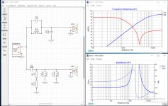
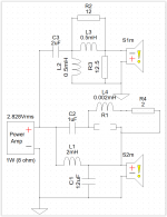
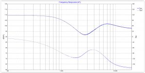
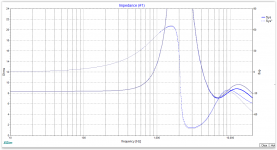
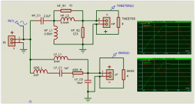
I made a xsim version of our modification. Pic1. The resulting frequency response is in pic2. And the resulting impedance response in pic 3.
Using the hold function we can see that the response for the woofer is identical except for the impedance above 10kHz.
In pic 4 I have simulated this up to 1MHz with and without the 2 ohm resistor in series with LF_C1(and the new 2uH ADD_L inductor). The difference can be seen in the plots to the right in this pic. Without the 2 ohms resistor we get a huge resonance at 112kHz from the tank circuit LF_C1 and the new 2uH inductor. How problematic this is in real life can be argued. 1 ohm almost eliminates this problem also.
Anyway, this modification alters the filter less than adding a 10 ohm resistor and will also increase the filters impedance above 100kHz. This will give added headroom for the switching residue of class D amps that operate at about 500kHz.
Attachments
Ok, I have had a Skype-chat with Armand on this for a while now, and my conclusion is that this filter is just so badly designed that one should just start over.
That's a real bummer. Bought the kit for the very reason of not having to design a crossover myself.
With no drivers I get no reading (0 ohms). With tweeter connected, I still get no reading. With woofer connected I get ~6 ohms.
Guess that means soldering is "fine" (working at least).
Done. I disconnected LF_C1, and issue is gone.
I then reconnected said capacitor, and disconnected LF_L1. Issue still present.
Good! Then swap LF_C1 from the 'good' board and see what happens.
Jan
Last edited:
Some amps do have trouble with tank filters sans resistance. Another thing, I would rarely use a tank cap that large. It tends to allow woofer ripple into the passband, as well as cause lower Z minima in the upper treble. An LC across the driver would likely be more effective at killing breakup, and the Low pass inductive rise would swamp the low Z minima of such a circuit.
Later,
Wolf
Later,
Wolf
Ok, I have had a Skype-chat with Armand on this for a while now, and my conclusion is that this filter is just so badly designed that one should just start over.
This is BS, one board works fine so the design is OK. It's not a very intelligent move to chuck a design because a part failed
Jan
- Status
- This old topic is closed. If you want to reopen this topic, contact a moderator using the "Report Post" button.
- Home
- Loudspeakers
- Multi-Way
- Crossover makes amp go into protection mode