Is this connection correct (marked in blue)
Yes, the tweeter is inverted. This is intentional by design.
LF L1 (2mH) probably has a short somewhere in the windings, try swapping it with the one on the other crossover. Or LF C1 (1uF) could be shorted
Okey, I'll try swapping when I get home from work
")
Just did this, and it's not the cap
I would double-check all connections related to this cap. If only to be able to check that off the list of possible causes.
I assume those caps on each board are exactly the same type/spec?
Do you have a signal generator and an ac multimeter?
Jan
See attached pics. Pretty sure its correct.
First is board layout.
Second is schematic based on board layout.
Third is re-arranged to make it easier to read.
Hope that brings some value!
Which is the cap you took out?
Jan
I would double-check all connections related to this cap. If only to be able to check that off the list of possible causes.
I assume those caps on each board are exactly the same type/spec?
Do you have a signal generator and an ac multimeter?
Jan
They are of the same type/spec yeah. I have a multimeter, which I've used to test a bunch of connections and compare them to the working crossover. I've found no difference so far.
By signal generator do you mean an oscillator? I could use my phone for that.
I reckon the idea is to test the high pass and low pass to see which circuit is faulty?
Unfortunately just connecting the bare crossover to the amp without any signal or drivers makes it go into protection.
Something that might be of note is the fact that the amp turns off protection after some 2-3 seconds. Then I have normal operation with sound for a sec or two before it goes into protection again.
Couldn't this mean that there might be an issue of the impedance falling and rising? I.e it falls below what the amp considers acceptable, and so it goes into protection. Then it rises again, and the amp turns off protection. And so forth. Just a thought.
Which is the cap you took out?
Jan
LF C2 (the 12uF cap)
There are only three possible components that will cause your fault.
Most likely is LF_C2, then HF_C1 or the horn/woofer is short circuit.
They are your only paths to common.
The LF_C2 seems to work when just connected directly in series with a woofer.
I can't get any ohm reading of it tho... As I've understood it, I should get a slowly rising resistance.
I'll test swapping the HF C1 (or did you mean the LF C1?) from the good crossover over to the bad.
No the HF_C1 as that is in series with the horn and if short circuit it will give full range on tweeter and damage the horn and possibly the amp.
A capacitor will read open circuit if good so no need to remove them if there is no connection at one end.
avtech has an excellent test with no drivers connected you should have an open circuit on the input as there is no DC path to ground.
A capacitor will read open circuit if good so no need to remove them if there is no connection at one end.
avtech has an excellent test with no drivers connected you should have an open circuit on the input as there is no DC path to ground.
Last edited:
Have you measured for continuity between in+ and in- with the tweeter and woofer disconnected?
No the HF_C1 as that is in series with the horn and if short circuit it will give full range on tweeter and damage the horn and possibly the amp.
A capacitor will read open circuit if good so no need to remove them if there is no connection at one end.
avtech has an excellent test with no drivers connected you should have an open circuit on the input as there is no DC path to ground.
In other words, if I do an ohm test on the positive and negative input terminal, I should get no reading right? (on just the board with no drivers connected).
And with drivers connected I should get ~6-7 ohms (8 ohms nominal)?
Yes, with no drivers you should have an open circuit reading if both HF_C1 and LF_C2 are blocking the meter's DC.
A resistance value might help identify whether HF_C1 or LF_C2 is short as you will see the resistance of either HF_L1 or LF_L1 depending on the path the short takes.
A simple check, so might be worth a try.
A resistance value might help identify whether HF_C1 or LF_C2 is short as you will see the resistance of either HF_L1 or LF_L1 depending on the path the short takes.
A simple check, so might be worth a try.
LF C2 (the 12uF cap)
We already know it is not LF_C2 (because using the other one from the 'good' board still gives the error).
Now, this cap is in series with the parallel combination of LF_C1 and LF_L1. If any of these (or the combination) has a very low impedance, that would explain the error. It would also explain that it makes no difference whether the speaker is connected or not.
Take out each of LF_C1 and LF_L1 in turn and see if the error is gone.
Jan
Just got a tip that LF_C1 and LF_C2 together will short the filter at high frequencies if the amplifier has the amp has a wide enough bandwidth and the caps has low enough ESR.
If that's the case, then it's a serious design flaw with the Volt 10 MK2 filter...
Do as AVTech suggested, measure the dcr without a load in place.
- As mentioned, all the inline capacitors should prevent any resistance from being read by your meter.
Next add the woofer load into the equation ( ie; after the network ).
- Your multimeter should now read a resistance that's the sum of the 2mH coil's dcr + the dcr of the woofer.
- If still you get a reading showing no resistance, then you're soldering ( of the 2mH coil ) is suspect ( meaning you have a cold-solder joint ).
Needs to be Said, I don't like your soldering job.
From your pics, you've made no attempt to create any mechanical connection between the trace-pads and the leads of the passive devices.
To rely on today's lead-free solder for good electrical connections is bad practice.
Those component leads should be bent over + touching the trace-pad, then held in place ( for soldering purposes ) by the tip of a straight-blade screw-driver while heat is applied to the trace-pad.
Also, capacitors should be heat-sinked when being soldered ( by hemostats, etc. ) to prevent heat damage ( especially important with today's solder that resists flowing ).
- It wouldn't hurt to heat-sink the coils and resistors when they are being soldered ( especially until your technique sharpens up ).
Considering all the above, I sort of doubt that DIYSG is to blame for your troubles ( though putting an inline resistor of 5R with that 1uF cap in the bass circuit, ought to satisfy UHF circuit stability ) .
Last edited:
Just got a tip that LF_C1 and LF_C2 together will short the filter at high frequencies if the amplifier has the amp has a wide enough bandwidth and the caps has low enough ESR.
This is a spectacular misunderstanding of how the filter works. It also glosses over the fact that the 'good' board works, well, good...
Why not follow an intelligent diagnosis process rather than randomly throwing up hypotheses?
Disconnect in turn L_C1 and L_L1, we get another step closer to it.
Jan
Last edited:
Have you measured for continuity between in+ and in- with the tweeter and woofer disconnected?
avtech has an excellent test with no drivers connected you should have an open circuit on the input as there is no DC path to ground.
With no drivers I get no reading (0 ohms). With tweeter connected, I still get no reading. With woofer connected I get ~6 ohms.
Guess that means soldering is "fine" (working at least).
Take out each of LF_C1 and LF_L1 in turn and see if the error is gone.
Disconnect in turn L_C1 and L_L1, we get another step closer to it.
Done. I disconnected LF_C1, and issue is gone.
I then reconnected said capacitor, and disconnected LF_L1. Issue still present.
With no drivers I get no reading (0 ohms). With tweeter connected,
I still get no reading.
The 0 ohms is NOT "no reading". It is a short circuit.
Infinity ohms IS "no reading" (open circuit).
The 0 ohms is NOT "no reading". It is a short circuit.
Infinity ohms IS "no reading" (open circuit).
Ok, my bad with the terminology.
To make sure, here's the reading without a load, and then with the woofer.
Attachments
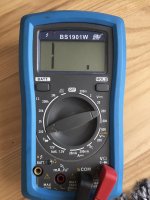
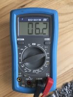
With no drivers I get no reading (0 ohms). With tweeter connected, I still get no reading. With woofer connected I get ~6 ohms.
Guess that means soldering is "fine" (working at least).
Done. I disconnected LF_C1, and issue is gone.
I then reconnected said capacitor, and disconnected LF_L1. Issue still present.
Another Test:
Replace all components to their original positions ( excepting one end of LF-C1 > keep it loose ).
- ( it doesn't matter which end you choose to lift, btw )
Then temporarily remove the 10R resistor ( from the HF portion of the circuit ) and then attach one end of the resistor to the loose end of LF-C1 cap. then attach/solder the free end of the 10R resistor to the point ( on the PCB ) that LF-C1 was originally attached to.
Add drivers to the network and then test again.
If the amp doesn't go into protection now then that means the LF notch ( consisting of L1 + C1 ) is indeed destabilizing the amp up in the UHF region.
That means the notch will need to be redesigned ( by adding a few more components) and will also need to be re-positioned.
Last edited:
- Status
- This old topic is closed. If you want to reopen this topic, contact a moderator using the "Report Post" button.
- Home
- Loudspeakers
- Multi-Way
- Crossover makes amp go into protection mode