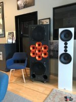
Hearing a CBT or any speaker in a hotel room for a few minutes is different from listening to a properly positioned speaker in an known environment with your own music. Patrick needs to rent a CBT and hear one in his home as he did with the SH50s to really compare. Otherwise we are talking apples and oranges.
Finally, many excellent speakers project sound that seems to float in the air and does not betray their sources. My open back three-way system provides that kind of sound. The Modified CBT24s also have a sound that you can listen next to them or any location in the room and not clue you that they are making the sound.
Finally, many excellent speakers project sound that seems to float in the air and does not betray their sources. My open back three-way system provides that kind of sound. The Modified CBT24s also have a sound that you can listen next to them or any location in the room and not clue you that they are making the sound.
I have a summer DIY speaker project. I believe Tekton DI is a great project to work on. I'm really wondering how It sounds ")
We already know tweeter model, midrange model, tweeter schematic.
What we don't know is the subwoofer model and subwoofer and midrange crossover schematic. Can someone help me to complete the puzzle?
We already know tweeter model, midrange model, tweeter schematic.
What we don't know is the subwoofer model and subwoofer and midrange crossover schematic. Can someone help me to complete the puzzle?
Considering what has already been determined, these three things are more conventional and shouldn't be difficult to find a solution to.
I wish I could have that knowledge base to figure it out.
Choose a woofer with enough sensitivity to keep up with the mids, then build the box. The mid and woofer can survive being run without a crossover (for now *), so you can try adding crossover parts and listening to the result. Maybe try a second order filter at the same frequency.
Another way you can do this is to look at Patrick's post #12. Build on this using xSim and include the mids in the mid/tweeter cross.
Your first woofer/mid cross can be much simpler, guessing an inductor and capacitor. In the future you can simulate, and you can measure. It will take time, and it will improve.
* It is better that before you start, you add a capacitor to the midrange drivers so that they do not handle bass. This improves power handling but it is also better for your amplifier. Still, you have room to experiment without too much concern. Maybe try a second order filter here. You could start a build thread and get help as you go.
I have a pair of Tekton Double Impacts and I am trying to understand the details of the tweeter array. I created the attached schematic from my pair.
Can any of you crossover gurus break this down and explain the functions of circuit?
Do you have details for ribbon value ?
Its fairly easy to model Tekton in Vituix. I put up the array and did a DSP XO, trying to optimize horizontal directivity. Here is a screenshot showing my results
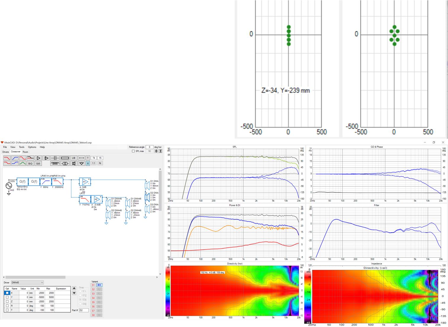
All drivers are DMA45s - 1.5" full range driver. My issue with these drivers is the response is too wide giving too much boundary interaction. I overlap all the drivers, low passing the outer columns and adjusting delay and SPL for best horizontal polars. The response narrows nicely compared to that of a single driver but I think the vertical response is too narrow so I would work on that.
I think next I will model the XO posted earlier in this thread.
Attachments

I finally managed to get the XO posted earlier captured and choose inductors for best polar responses. I made no effort to equalize the magnitude response. The DMA45 has a rising response in the HF that makes it good for line arrays but which would definitely require a trap in a passive XO.
The first horizontal inductor, 560 uH determines how high the two drivers above and below the central driver are allowed to play and thus control the vertical directivity to a large extent. The 2nd horizontal inductor controls how high the drivers in the outer columns play and thus controls the horizontal directivity. You can see the filter characteristics in the middle right graph of the screenshot

These are really nice polars to work with for completing the loudspeaker design with vertically flanking midwoofer and woofer pairs. Keeping the horizontal response width to below 45 degrees for much of the range helps eliminate early reflections from adjacent walls. The too narrow vertical directivity of my first post has been corrected, perhaps over corrected...but I think I would need more drivers in the central column to narrow it significantly
The first horizontal inductor, 560 uH determines how high the two drivers above and below the central driver are allowed to play and thus control the vertical directivity to a large extent. The 2nd horizontal inductor controls how high the drivers in the outer columns play and thus controls the horizontal directivity. You can see the filter characteristics in the middle right graph of the screenshot
These are really nice polars to work with for completing the loudspeaker design with vertically flanking midwoofer and woofer pairs. Keeping the horizontal response width to below 45 degrees for much of the range helps eliminate early reflections from adjacent walls. The too narrow vertical directivity of my first post has been corrected, perhaps over corrected...but I think I would need more drivers in the central column to narrow it significantly
Attachments
I am no XO expert but this is what it looks like to me:
dave
I finally managed to get the XO posted earlier captured and choose inductors for best polar responses. I made no effort to equalize the magnitude response. The DMA45 has a rising response in the HF that makes it good for line arrays but which would definitely require a trap in a passive XO.
The first horizontal inductor, 560 uH determines how high the two drivers above and below the central driver are allowed to play and thus control the vertical directivity to a large extent. The 2nd horizontal inductor controls how high the drivers in the outer columns play and thus controls the horizontal directivity. You can see the filter characteristics in the middle right graph of the screenshot
These are really nice polars to work with for completing the loudspeaker design with vertically flanking midwoofer and woofer pairs. Keeping the horizontal response width to below 45 degrees for much of the range helps eliminate early reflections from adjacent walls. The too narrow vertical directivity of my first post has been corrected, perhaps over corrected...but I think I would need more drivers in the central column to narrow it significantly
Have you considered replacing the central driver with a tweeter and use the full-rangers as you laid them out?
Actually I have although this time i arrayed TC9s with central tweeter and used DSP in XO
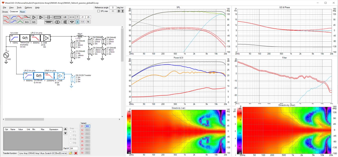
the room response curve in the middle graph (orange) just has wall reflections enabled. Due to directivity and 45 degree toe in, they are very limited. If I had enabled them, you would see a lot of reflection nulls shrinking as frequency rises again due to directivity.
From one point of view, the dispersion of the OC25 tweeter is too wide, its tamed be the array but still widens above the 8 khz XO. The DMA45 didn't have that problem but one probably wants a driver with higher power handling and efficiency to handle the top range by itself
Attachments

- Hi, I was wondering about their Polycell 15 speaker, has anyone heard it? --- ANd more importantly how does it work - are they using compression drivers instead of tweeters for their array as it seems? - ANd how can it work if the small horns are so far apart???? - Do they have to change the crossover frequencies... going lower because of the horn / composite midrange drivers distance being a lot further apart????
I have read many patents, and this is far and away the worst patent I've ever read.
A few gems from the patent:
"According to embodiments of the invention, new and improved transducers (a woofer for example) are specifically designed to match or more closely match the mass of the musical instrument producing the music."
and:
"According to additional implementations of the invention, one or more array(s) of very small transducers with minimal moving mass with or without separate amplification work in tandem grouped closely together to reproduce the lowest audible frequencies while keeping all related overtones completely intact. In one implementation a long column of small transducers quickly switches and/or cycles on and off with precision—even switching at speeds faster than that of the speed of sound consecutively so low frequencies can be continually reinforced over the length of the column and quickly be acoustically multiplied. High sound pressure levels and intensity are realized from the length of the column (low frequency wavelengths are long) and the overtones are left un-attenuated and intact.
This effect could be compared to frames-per-second in movies and videos. The moving frames provide the viewer with a flowing and precise image. The high speed switching of many multiple transducers will produce an acoustic effect comparable to that of many frames-per-second of video. An example illustrates the concept: lighting and its audible result called thunder in nature could be thought of as a very long column (a line source) of sound. Potential energy is high, the mass is low, and its speed of propagation is fast. The resultant acoustic event literally shakes windows and houses with great intensity. A scaled-down high-speed, low mass switching acoustical device roughly simulates the way thunder propagates from top to bottom through our atmosphere in nature. This type of device would have potential for very low frequencies to be realized using small transducers with great potential resulting intensity while keeping overtones and resultant waveforms intact."
Another one:
"Commonly used loudspeaker transducers (e.g. transducers used for tweeter 12, midrange transducer 14, and woofer 16) typically have on average twice to ten times (and often even more) the moving mass of the vibrating component of most vibrating and resonating musical instruments and devices producing the original musical event. By way of examples of vibrating components of musical instruments, such vibrating components include strings (for string instruments such as violins, cellos, harps, and the like), membranes (for many percussion instruments such as drums), and air masses (for wind and brass instruments such as oboes, saxophones, trumpets and tubas). As a specific example, the vibrating and resonating moving mass of the open E string (41 Hz) on an electric bass might have a string mass of 20.9 grams (a length of 34.5″) and produce a 41 Hz fundamental tone with all its related overtones. When played, the string produces a specific resultant wave with certain overtones.
When that resultant audio wave is recorded and then fed through a loudspeaker with just twice the moving mass of the original string mass, attenuation of the fundamental frequency and of the overtones is observed. The highest frequencies are skewed the most prominently and a dramatic low pass filtering effect occurs (the highest frequencies are attenuated more and more going up in frequency). Additionally, a slower acceleration and a slower braking effect of the transducer is observed due to its heavier mass. The result is a skewed and inaccurate produced waveform and the reproduced event does not sound like the original musical event. Describing this negative attribute is simple: the music is not as lively or energetic sounding. The sound is mellowed out, often described as “warmer” and dampened. Efficiency and intelligibility is also lowered and degraded."
Well I was feeling guilty for not digging up that patent; no longer. Its a shame they felt the need for that BS because the basic concept appears to be sound per my simple simulation.
Now it strikes that I've seen a similar picture (of a central driver surrounded by other drivers) before. Patrick, I'm sure you can you guess where - in the Danley Synergy patent!
Now it strikes that I've seen a similar picture (of a central driver surrounded by other drivers) before. Patrick, I'm sure you can you guess where - in the Danley Synergy patent!
If you're trying to get an array of identical drivers to work together (like the Tekton array) the rule of thumb is that your upper limit is:
Center-to-center spacing / 3
For instance, Monte Kay built a CBT speaker using 1" Aurasound speakers. The center-to-center spacing is about 1.5". That would indicate an upper limit of 3khz. (13500 / 1.5" / 3 = 3000hz)
Approx. 30 kHz, not 3 kHz
- Home
- Loudspeakers
- Multi-Way
- Help Understanding Tekton Tweeter Array Schematic?