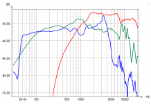
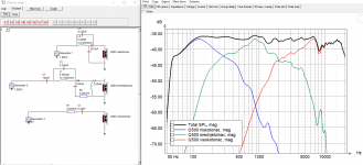
I really don't have a clue. I've made few measurements of raw drivers of my LS50 just to see what the drivers look like. I'm waiting for my friend to arrange renting of closed basketball court in elementary school nearby so we can measure it at 2.5m height and with gate at about 10-11ms.
What ever they've done, i think i can do better so i'm not relying on their design choices because i have different goals. I need the most accurate sound i can get out of them and they've made it "the smoothest sounding". That's not my cup of tea. I don't like my loudspeakers to be politically correct
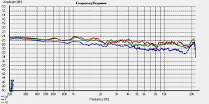
On topic - every UniQ Kef has (more or less pronounced) dip at 8kHz. That is product of their tangerine phase plug and is present only on axis. Off axis it disappears. Here's measurement of my modified Kef R300 on axis, 15 deg and 30 deg off axis:
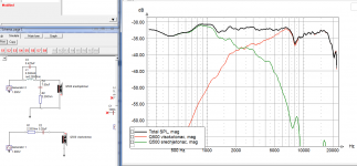
Slightly modified your Q500 midrange frequency response looks like this - it should already sound much better because you don't listen your highs through midrange cone breakup:
Factory crossover
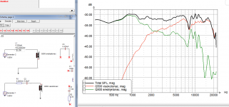
Slightly modified
What ever they've done, i think i can do better so i'm not relying on their design choices because i have different goals. I need the most accurate sound i can get out of them and they've made it "the smoothest sounding". That's not my cup of tea. I don't like my loudspeakers to be politically correct
On topic - every UniQ Kef has (more or less pronounced) dip at 8kHz. That is product of their tangerine phase plug and is present only on axis. Off axis it disappears. Here's measurement of my modified Kef R300 on axis, 15 deg and 30 deg off axis:

Slightly modified your Q500 midrange frequency response looks like this - it should already sound much better because you don't listen your highs through midrange cone breakup:
Factory crossover

Slightly modified

Last edited:
I just quoted you from last post on page 7.
Bottom line is that we don't need MF HF reversed polarity or LF MF reversed polarity when taking measurements used for deriving sim files.
5.zip should be the one holmimpulse - Google Drive
Just curious, is it reversed in your LS50?
The tweeter of the LS50 is connected in reverse polarity.
Attachments
Sorry, I've uploaded the 8 where the LS and the LS MF are both covered. Can you please tell me how to check it?
I really wouldn't know what you mean by covered or uncovered.
All you need to do is to connect all three drivers (normal polarity, + on + and - on -), put the mic on a stand on tweeter axis 1m distance and make those 5 measurements. Mic position and amplifier volume shouldn't be messed with during all 5 measurements. 3 pieces of wire, one for each driver, that sticks out of the cabinet so you can connect it the way explained in that PDF i posted before. I made .txt files from 5.zip you've uploaded and i don't get anything resembling a real situation.
Sorry what I meant by covered is I covered the hole on the back properly.
I measured with a way how you described it, I never touched any volume.
Anyways, I made a new measurement, uploaded here: holmimpulse - Google Drive
What I can't understand, in low freqs they all look similar.
I measured with a way how you described it, I never touched any volume.
Anyways, I made a new measurement, uploaded here: holmimpulse - Google Drive
What I can't understand, in low freqs they all look similar.
That's because that amount of gating allows good resolution down to 300Hz. Everything under that frequency isn't right. Anyway, i think i'll manage to do something with these last measurements. I'll get back to you by this evening with results.
Thank you very much! I was trying to do the lapping in Xsim and in VituixCad as well, in Vituix I couldn't get really close, in Xsim is not that bad.
Looks better than the original. Maybe the base is too high, but as I mostly listen vinyl, it doesn't matter.
Have you figured out the offsets?
Can I put back the crossover and close back the cabinet?
Thanks!!!
Hi, yes you can close the cabinets.
This is a little dressed up version of the five minute crossover i simulated earlier today. Regardless of time spent to simulate it, it does look like an obvious improvement on factory crossover.
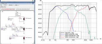
Offsets worked very good with midrange and tweeter, little less precise with woofer and midrange, but that is a product of short gate and rather high merging. It looks like this.
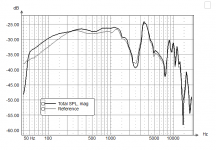
For tweeter all offseta are 0
For midrange Z offset is 2,5mm in front of the tweeter
For woofer Y offset is -300mm and Z offset is 10mm behind the tweeter
You can set the level of midrange in regard to bass with resistor R3. Use at least 10W resistors. Capacitor C7 will be expensive if you look at some high end manufacturers but since Kef in their R series uses bipolar electrolytic capacitor bypassed with some small value foil capacitor, i think you'll be fine with foil capacitors you can find on ebay. I've bought some nos Vishay foil capacitors 63V/22uF quite cheap from ebay.
Bare in mind that this is simulation based on data i was given. Longer gate, higher resolution, measurements off axis up to at least 90 degrees and i would be much more confident in what i simulate to be very close to end version of crossover. This one will likely need some tweaking by ear. I tried to save as much of the components that are already there to minimize the cost of reworked crossover.
I'll simulate one more version aiming to get the bass under 100Hz a little higher which usually means that everything else must go down so at least 3dB lower sensitivity in regard to this one.
cheers
This is a little dressed up version of the five minute crossover i simulated earlier today. Regardless of time spent to simulate it, it does look like an obvious improvement on factory crossover.

Offsets worked very good with midrange and tweeter, little less precise with woofer and midrange, but that is a product of short gate and rather high merging. It looks like this.


For tweeter all offseta are 0
For midrange Z offset is 2,5mm in front of the tweeter
For woofer Y offset is -300mm and Z offset is 10mm behind the tweeter
You can set the level of midrange in regard to bass with resistor R3. Use at least 10W resistors. Capacitor C7 will be expensive if you look at some high end manufacturers but since Kef in their R series uses bipolar electrolytic capacitor bypassed with some small value foil capacitor, i think you'll be fine with foil capacitors you can find on ebay. I've bought some nos Vishay foil capacitors 63V/22uF quite cheap from ebay.
Bare in mind that this is simulation based on data i was given. Longer gate, higher resolution, measurements off axis up to at least 90 degrees and i would be much more confident in what i simulate to be very close to end version of crossover. This one will likely need some tweaking by ear. I tried to save as much of the components that are already there to minimize the cost of reworked crossover.
I'll simulate one more version aiming to get the bass under 100Hz a little higher which usually means that everything else must go down so at least 3dB lower sensitivity in regard to this one.
cheers
Last edited:
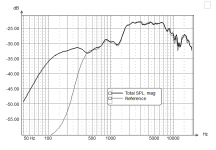
Here's low sensitivity full baffle step.
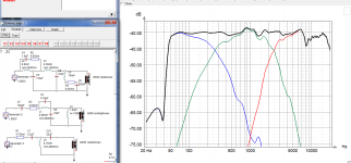
Although it does look good, i'd be reluctant to make this crossover without sim files derived from measurements with gate under 9ms. Too much large component values - it would be pricey. Not saying that Kef Q500 doesn't deserve it but it needs to be done with as little error possible.

Although it does look good, i'd be reluctant to make this crossover without sim files derived from measurements with gate under 9ms. Too much large component values - it would be pricey. Not saying that Kef Q500 doesn't deserve it but it needs to be done with as little error possible.
I just got back a message from a uni regarding they anechoic chamber yesterday. So I might will be able to use it if I want. Still needs to be signed by the head of department, but I might could go.
Originally I wanted to replace the factory caps and coils as they seems cheap and thin.
So I think do not worry about that part.
And why the C7 would be the most expensive? C8 is 350uF : D That would be crazy.
Also I can build the crossover from cheaper parts first then upgrade them. But I'm not sure I would be able to work with it later, mostly because this design looks so complicated to me for first.
350uF capacitor is large but it is cheap. Since it is in notch filter that is centered at around 90Hz, i'd advise you to buy 2 polarized electrolytic capacitors 680uF/100V and connect them in series back to back (- on -). Then measure it with dats and add foil capacitor in parallel to get to 350uF. C7 however needs to be as good as you can afford so no bipolars or any electrolytics for that matter. I like to make that large capacitors out of 22uF because of later tweaking. If you buy 100uF and it doesn't work as supposed to, you're stuck with it (unless you need higher value). Making it out of few smaller ones gives you a degree of freedom. I've made mine out of 4x22uF and 1x10uF connected in parallel.
Last edited:
350uF capacitor is large but it is cheap. Since it is in notch filter that is centered at around 90Hz, i'd advise you to buy 2 polarized electrolytic capacitors 680uF/100V and connect them in series back to back (- on -). Then measure it with dats and add foil capacitor in parallel to get to 350uF. C7 however needs to be as good as you can afford so no bipolars or any electrolytics for that matter. I like to make that large capacitors out of 22uF because of later tweaking. If you buy 100uF and it doesn't work as supposed to, you're stuck with it (unless you need higher value). Making it out of few smaller ones gives you a degree of freedom. I've made mine out of 4x22uF and 1x10uF connected in parallel.
Thank you very much for all your help!
What do you think what should be the next step? Wait a bit so maybe I could remeasure the speakers in an anechoic chamber?
No problem. This is fun for me to 
First, i'd make that slight modification to speakers from this schematic.
https://www.diyaudio.com/forums/att...872-kef-q500-crossover-blaga-modifikacija-png
Don't touch the woofer but use 6.8uF and 2.2ohms shunt with midwoofer, buy 0.47uF small foil cap and 0.5mH coil (per speaker). It is mild change but quite effective. I order my air coils from hificollective.
Make the mod and listen how it sounds and if it makes a difference in clarity to you. If you're satisfied, then wait some more untill you do the anechoic chamber measurements. You should ask them down to what frequency the chamber is effective. If it is over 300Hz then you can use it but the results shouldn't differ that much from what you've achieved in your flat.
As for large capacitors, there are quite a few over at Madisound also: MDL Electrolytic Capacitors 250VDC
Last edited:
- Status
- This old topic is closed. If you want to reopen this topic, contact a moderator using the "Report Post" button.
- Home
- Loudspeakers
- Multi-Way
- KEF Q500 new crossover
