At the bottom of the thread On the Axi there’s little metal tabs sticking out.... am I supposed to respect those as limits or are those supposed to bind threaded post into the compression driver? I bought lock nits with nylon...the amount of force to get the nut to turn push it past the metal tab...I figured I’d ask before I did the rest...
A very slow creep towards progress...I’ve got blue paint in acrylic, spray paint, and alcohol ink, as well as mica powder lol...
I have a question; In regards to edge rounding and chamfer...I can possibly cut a chamfer with my skill saw....the width of midrange baffle is 32” and I know I’ll crossover no higher than 500hz...this is below where edge diffraction might have strong effects if any....
Should I cut chamfers in this enclosure? Is there a ratio to how big they should be vs how wide my front baffle is.
I realize that I might want to complete a matching width baffle for the horn? Why is it that some other designs have a smaller baffle width higher in the register....what are the benefits and perceived differences vs a baffle width that is equal from top to bottom?
How big you can cut anything will depend on the thickness of the baffle and cabinet sides. You have fusion so you can model how much material will be left after any chamfering.
Basic article | Baffle geometry
This is a good working through of the effects of baffle shapes and edge treatments.
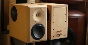
For this I would use the socket head cap screws shown above by mark100, (I wouldn't use stainless though) with insert nuts. You can torque these down pretty tight and remove them as many times as you like. How many will depend on the thickness of material and if you have braced the panels. The stiffer and flatter the panels the less screws will be needed to hold them in place with an airtight seal.So I'm going to have to make several panels, re-accessible, for the long term... I'm trying to hypothesize a good screw per inch for these panels....any ideas?
This from Hificompass seems like a reasonable amount for a small speaker
Attachments
Yes I have 100 of those screws and matching inserts.. . looks to be approximately 2.5" per screw...
Regarding the chamfer... You know what...I haven't finalized anything yet....I can afford a little more depth on the cabinet...let me see what I can do for the sake of doing it the right the first time....the irony is in how many times I just edited this post.....=)
Regarding the chamfer... You know what...I haven't finalized anything yet....I can afford a little more depth on the cabinet...let me see what I can do for the sake of doing it the right the first time....the irony is in how many times I just edited this post.....=)
Last edited:
I don't think it's sloppy but it is hard to say exactly what effect another object near the horn with sharp edges could do to the overall pattern, given the effect that the woofer cone will make probably makes it even less important.
I never discount the visual impact and matching chamfers would most likely look better. Model it and see")
I never discount the visual impact and matching chamfers would most likely look better. Model it and see
Attachments
I realize that I might want to complete a matching width baffle for the horn? Why is it that some other designs have a smaller baffle width higher in the register....what are the benefits and perceived differences vs a baffle width that is equal from top to bottom?
Baffle shape is about polar response, controlling reflections, so depends on the performance needs of the app in prosound and more cosmetic in the consumer marketplace.
Tapered at > 12 deg [included] is often used to keep eigenmodes from fully developing [they rapidly decay away].
Depends on the baffle size, shape, horns or not and how it interacts with the room, but the basics is that the narrower it is, the more 'open' it sounds due to much more of the sound falling away as the speaker's polar response is narrowing up with increasing frequency.
Other news...I've got the firmware updated and software is functional for the crown amp input cards...I've got to grab some wire to connect through the phoenix connectors before I can test the axi on the horn...
Attachments
Last edited:
The more I think about it...my end goal should be to take a selected horn and combine it with the mid cabinet....just like others have down with waveguides and such.
an mid-high array of small drivers (on-wall - which gives additional ~6 dB of dynamic range) and a woofer that is boundary coupled (additional ~12 dB of dynamic range), crossed around 300 Hz, is a viable alternative IMHO
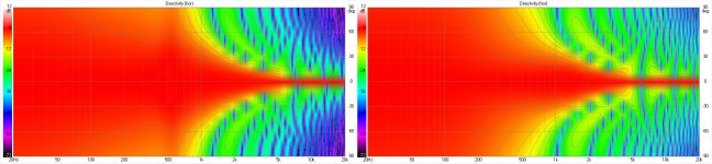
No, not "terribly dissimilar", they both describe incredibly "beamy" horns, reducing from around 90 degree at 1000Hz to less than around 5 degree at 5000Hz and above.(15m left, Axi right) - This is what Vituix shows me... The polars aren't terribly dissimilar are they?
That bad of a horn would be hard to build even if you tried to

They both can't describe beamy horns because one is a 15" woofer lol....A rectangle source is the best I could do for the Vituix dispersion Tool.....surely the real polar isn't so beamy.... the dispersion around where the source width looses directivity is more important to look at here....the beaming of the upper register is exaggerated, surely, by the bad modelling representation.
Question....is it sloppy if I build a box that I would have to destroy to open again?
Question....is it sloppy if I build a box that I would have to destroy to open again?
- LMAO!!!!Yes laser - when everything get dark (forever?) you're in the sweetspot
Don't be afraid of building sloppy prototype, just consider it as one and take most out of it. Then take what you've learned and build the final enclosure which you won't have to open again (if you learnt from the proto). Have fun!
Ps. a box can be destroyed multiple times, just patch it up in between.
Ps. a box can be destroyed multiple times, just patch it up in between.
The rectangle isn't going to help you at all, the 15" woofer will beam like a laser high enough in frequency. You can see that in the simulation I posted before.They both can't describe beamy horns because one is a 15" woofer lol....A rectangle source is the best I could do for the Vituix dispersion Tool.....surely the real polar isn't so beamy.... the dispersion around where the source width looses directivity is more important to look at here....the beaming of the upper register is exaggerated, surely, by the bad modelling representation.
If you are using MDF or particle board, I would highly recommend Confirmat-style screws. I really like them as they are quite strong and the same hole can be used at least a few times without falling apart. I got mine from Lee Valley.Yes I have 100 of those screws and matching inserts.. . looks to be approximately 2.5" per screw...
Regarding the chamfer... You know what...I haven't finalized anything yet....I can afford a little more depth on the cabinet...let me see what I can do for the sake of doing it the right the first time....the irony is in how many times I just edited this post.....=)
Knock-Down Screws - Lee Valley Tools
The "Lo-Root" screws might work, too, but the photos don't exactly inspire confidence.
- Home
- Loudspeakers
- Multi-Way
- Is it possible to cover the whole spectrum, high SPL, low distortion with a 2-way?