Thank you so much for this! My monitor died so I can’t reply in the fashion that I’d like or run horn resp. I’m currently shopping for a new screen.
So thanks for you input, it is needed desperately lol. The people on Martin Kong’s forum can’t get over the freq curve of the woofer and how it’s like 6db higher in the midrange lol I tell them it’s not the average driver but it doesn’t sink in and they my enclosure is not right. They did help me edge along to trying new ideas which got me here so...
I think you think the 18h+ is crossing to the Axi, it’s crossing to 15m
Also, your graphs have step and impulse response? I’ve been trying to figure out the difference for a long time? Care to explain?
Last edited:
Sorry for the typos, my phone post are the worst. Martin King is the name I meant to type.
If anyone else wants to try and design a TL for the 18 in horn resp, go for it. 30hz 115db 15xmax well damped are the minimum requirements, if you can improve on that, so be it.
If you could do an impulse/step sim for my first TL design, that’d be awesome
If anyone else wants to try and design a TL for the 18 in horn resp, go for it. 30hz 115db 15xmax well damped are the minimum requirements, if you can improve on that, so be it.
If you could do an impulse/step sim for my first TL design, that’d be awesome
mathematically, the step response is the integral of the impulse response.
Intuitively, though, think of a step as a driver cone going instantaneously from center to maximum excursion and staying there. But you can't hold the cone at maximum excursion unless response is flat down to DC. So in a wideband system, the step response is (or should be) a sharp initial rise followed by a slow decay, i.e. triangular, the slower the decay the lower the bass response extends.
Common wisdom is impulse response shows mainly HF response and presence of delayed reflections. (In the TL, you see the reflections from the ends of the transmission line.) Step response shows the bass response.
Using both TD15M and TD18H+? then its not a 2-way!
Thank you for explaining, first time I’ve found a laymen’s definition. The 18h+ is the subwoofer ") so it can be argue both ways! From 30hz to 100hz is initial starting point for crossover.
so it can be argue both ways! From 30hz to 100hz is initial starting point for crossover.
A few pages back I posted a design with 3D model. Can you run this design in your programs please? This design is much more a classic TL and much more dampened...maybe the results can provide useful information about what even more damping does to the response. This design is still more efficient than a sealed box....if it leads to better sound quality then I’d resort to a design more like it.
so it can be argue both ways! From 30hz to 100hz is initial starting point for crossover.A few pages back I posted a design with 3D model. Can you run this design in your programs please? This design is much more a classic TL and much more dampened...maybe the results can provide useful information about what even more damping does to the response. This design is still more efficient than a sealed box....if it leads to better sound quality then I’d resort to a design more like it.
Last edited:
The names are silly btw....its all just a Horn to me......
Technically, they're all just 1/4 WL TLs, the names are just for us to have a clue what type is being referred to.
GM
A few pages back I posted a design with 3D model. Can you run this design in your programs please? This design is much more a classic TL and much more dampened...maybe the results can provide useful information about what even more damping does to the response. This design is still more efficient than a sealed box....if it leads to better sound quality then I’d resort to a design more like it.
Can you post the HR filling screen for this model ? That why I'll be able to match your results...
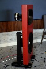
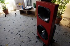
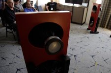
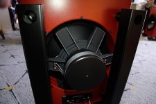
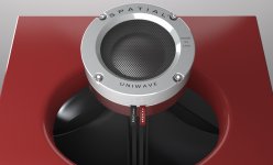
Not to disrupt or interfere with the debate on TLs, but I came across another 2-way system worth mentioning. Even though it won't hit 115 dB, it's a rather straightforward design and therefore seems like a proper candidate for a DIY clone.
Previously, another loudspeaker of the same brand was discussed, the Spatial X5, that uses the FaitalPro HF10AK + XT1086 and 12 + 15" Eminence Deltalite woofers.
The X1 is (was?) Spatial's top model, a 2-way dipole system featuring the 18Sound XT1464 + customized Radian 950Be PB with open back and AE Dipole 18".
The most intriguing aspect of the X1 is the wideband application of the horn driver combo, 300Hz - 20kHz!
The XT1464 looses pattern control around 600Hz and doesn't load the driver very well below 500Hz.
Yet, according to Clayton Shaw of Spatial Audio, there wasn't any noticable difference between 300 and 600Hz... Interesting.
The SPL limit of the AE Dipole 18 is 110 dB, which in practice means the Be diaphragm rarely sees more than 1 Watt.
The X1 received some raving reviews, topped off by the attendee of LAAS 2017 who asked to buy the complete demo system, which was delivered and set up right away. Nevertheless, the X1 appears to be NLA, as there's no reference to the speaker on the company's website.
Attachments
Last edited:
Can you post the HR filling screen for this model ? That why I'll be able to match your results...
It’s 100% length fill, and fill until you xmax crosses 115db at 777watts. When I hook another monitor up I’ll get the screen shot.
Last edited:
but what is the Fr? and what materiel is it representative of?
I use 4000 which I think corresponds roughly to pink fluffy fiberglass but I don't recall where I got the number from originally. rigid fiberglass of various densities is progressively higher. Filling the pipe with those over damps it. Just a little bit of fill and it starts looking somewhat like a bass reflex..
If anybody has good numbers or can confirm mine, please speak up!
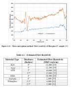
but what is the Fr? and what materiel is it representative of?
Loose polyfil is what HR calculates in the Wizard, no clue how it relates to fiberglass insulation, though maybe you can figure something from my MLTL sim that I know from experience that with one side, top, back lined with 1" OC 703 fiberglass duct board it will knock down HR's Fb peaking ~ 6 dB, so normally this is the max I use for this type alignment.
HR predicts it as being ~3 lbs of polyfil evenly distributed 100%. If more damping is needed, then I would do it by 'critically damping' the vent 'in situ' since I've found no simple way to convert stuffing density to [layers] of some material
Anyway, since camplo didn't set a size restriction nor what 'well damped' means, here's my default 'well damped' 10:1 CR, Vb = Vas, Fb = Fs ML-TQWT I did back when I found out what driver he bought.
GM
Attachments
Hi GM:
Thanks for that. This is my first look at this type of enclosure and I'm enjoying the exploration. I thought I had to enter a known value of Fr but I see from playing with your model that HR calculates the lbs of polyfill needed to get the Fr entered and the achievable Fr range with polyfill is 100 ++ which is what Camplo needs to get his response. Except for the size, these things are almost too good to be true.
And David clued me in to use of F9 key to export SPL data from the Tline wizard so I can see a real IR.
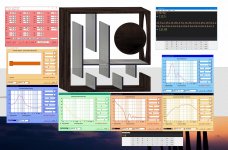
So with the added volume of paneling, a ~300 liter TL fits inside of ~414liters. The design in the 3D model is about 300 liters, external box dimension, at 0.5 inches wall depth, somewhere close to the 30x30x30....my last design is ~320 liters, with potentially less folding so I think box size is still approximately the same.
Loose polyfil is what HR calculates in the Wizard, no clue how it relates to fiberglass insulation, though maybe you can figure something from my MLTL sim that I know from experience that with one side, top, back lined with 1" OC 703 fiberglass duct board it will knock down HR's Fb peaking ~ 6 dB, so normally this is the max I use for this type alignment.
HR predicts it as being ~3 lbs of polyfil evenly distributed 100%. If more damping is needed, then I would do it by 'critically damping' the vent 'in situ' since I've found no simple way to convert stuffing density to [layers] of some materialstretched tightly over the vent, though if you cover both ends of the vent you can use HR to stuff it same as the cab.
Anyway, since camplo didn't set a size restriction nor what 'well damped' means, here's my default 'well damped' 10:1 CR, Vb = Vas, Fb = Fs ML-TQWT I did back when I found out what driver he bought.
GM
Just hooked up a spare monitor and now I am able to play. I looked at your design GM, the first screen I was really interested in is of course the impedance....since every one seems to be shy on the subject maybe you can provide some wisdom. In your design peaks just under 70ohms...what is your reasoning and justification for this...you are last person I'd label as coincidental. Do you think there is anything to gain by using a more dampening design which results in a lower impedance which in turn represents less resonance and more diaphragm control.
Not really, look at the GD, which is low plus quickly decays away before our hearing acuity improves enough:
Discussion of Group Delay in Loudspeakers
Discussion of Equalizers and Group Delay in Loudspeakers
GM
Discussion of Group Delay in Loudspeakers
Discussion of Equalizers and Group Delay in Loudspeakers
GM
Ty for the links, that info went into my library.Also thanks for whipping up a TL model. IF I gave you the stipulation of no taper....could you design something with common attributes as the last? I'm not confident about building a folded tapered TL...and it looks like you have used an offset...I've basically started my designs as a back-loaded horn to ensure no offset and the driver being face front. Seems to make the most sense for fitting it into a box. I think the size is just about right, bigger than my designs but the are still close. I guess it wouldn't hurt for me to also attempt a model of a tapered line, it just doesn't seem like it would be accurate...folded and all.
Is not the impedance peak in connection with actual decay times like shown in the impulse models done by nc535...and less decay is better? or...? wha? All the models I looked up (Focal & PMC) had impedance lower than 30-20ohms. Just wondering why...70ohms is still less than the 120-140ohms I've seen in the undampened models...what does it all mean.
nc535 are you available, I am attempting to do what you did and turn a frequency repsonse into an impulse....so far it seems easier to turn an impulse into a frequency response...lol
ps - I changed the offset and the performance stays pretty much the same so I guess tahts a non issue. I'm just unsure at the moment about folding tapers.. I like how you were able to pull off a larger terminus.
Last edited:
You're welcome!
Honestly, never gave it much thought. Freddy asked me similar before that thread with reference to an Altec driver's very high impedance spikes, but when that thread droned on n' on I finally asked the only remaining 'Altec' engineer at the distributor that knew me from decades earlier and he said ignore it as my well damped design routines ensure it's never an issue, i.e. basically 'much ado about nothing' in my case.
GM
I see...I also have looked at your model with the "setting" changed to conical...the straight walls make more sense to me in accord to what I am willing to do with a piece of wood... it brings the volume down to 338 liters and response doesn't lose the spirit of your original programming =) . This design, is more efficient than the 2 I did, and the one that Nc535 did. I call his another design because his dampening style isn't that of my design and his output results are different. Either way, I am interested in getting the most efficiency as possible with close consideration of sound quality. You like it, I love it,
- Home
- Loudspeakers
- Multi-Way
- Is it possible to cover the whole spectrum, high SPL, low distortion with a 2-way?