But that's not just the 2384 is it?
Looks like the whole 4722 - and the dip in vertical beamwidth around 600 Hz is the interaction of the horn with the stacked woofers.
Or so I suspect, I have an idea about how to better optimise this, do you have any data on the 2384 alone?
Best wishes
David
Hi Dave, I have on axis response of just the waveguide, but no polars. I believe the waveguide itself is a 90 x 50 pattern. I do have a spinorama for the system. The waveguide loses vertical directivity at 1 kHz. I use digital linear phase XO with steep slopes and is time aligned to the stacked woofers. Curious about your suggestion for optimization?
Hi Mitch,
40 x 20 is certainly a problem in any system, but 100 x 100 is wider than I think optimal, even in a small room. I would love to be able to use a narrower 70 x 70 device, but there isn't a feasible woofer that can do that except at >> 1 kHz. Hence 90 x 90 seems to be the highest DI that I found feasible to build cost effectively.
Hi Earl, the JBL M2 is a 120 x 100 and was thinking along those lines. But I hear you on the 90 x90. Where can I get them? ;-)
Curious about...optimization?
I have 15" woofers (JBL 2226) and 1.5" compression drivers (JBL 2453, spare 2447), so broadly similar use case to this thread, you, Wayne Parham and, just a little less, Earl.
My room suits a 90 to 70 horizontal beam-width, I aim nominally at 80.
Where I differ from Earl is that I aim for a little narrower vertical, around 45 to 50, partly because the house structure is concrete and brick and reverb is hard to control.
The optimisation of the directivity of non-axisymmetric horn + woofer is a problem that I haven't seen much written about.
Bill Waslo pointed me at Wayne's posts and they made me think.
When I did some calculation for the 80:45 ratio I came up with an answer a little different.
Somewhat to my surprise what looks to have promise is close to a square horn mouth.
This needs a little nip-and-tuck from mathematically idealised horn but should be minor.
Then the woofer is placed sufficiently close to the horn to hold the directivity but stop the waist band around crossover.
For a double woofer the extra distance is problematic if stacked vertically.
Vertical polars would improve if they were placed horizontally, obviously horizontal polars would need attention, not sure how this would play out in the 4722.
My idea really needs to be confirmed with a FEM/BEM simulation and I have started on ABEC3.
But it's a lot of work and I have physical speakers to finish first.
Best wishes
David
Hi Dave, what are your optimal listening distance goals
If not a traditional mtm, one that resembles an upside down V seems like a good idea. In this thread it is discussed, how horizontal issues are more dramatic than vertical, lobe or time based. Yet there are some designs out there that run dual 15s horizontally. The augspurgers come to mind
If not a traditional mtm, one that resembles an upside down V seems like a good idea. In this thread it is discussed, how horizontal issues are more dramatic than vertical, lobe or time based. Yet there are some designs out there that run dual 15s horizontally. The augspurgers come to mind
Last edited:
Hi Dave, what...distance
The speakers are in the corners, across the narrower dimension, about 3.6 m apart, centre to centre.
I listen at about 3.6 m, classic equilateral position, in fact the whole room is classic IEC standard dimensions.
If not a traditional mtm...
My speakers are just horn and woofer, similar to a JBL M2 or Earl's Summa. Plus subs of course.
In this thread it is discussed, how horizontal issues are more dramatic than vertical, lobe or time based. Yet there are... dual 15s horizontally
I am in accord that horizontal are more important, probably why optimisation of verticals is not much analysed.
But to keep excellent horizontals and improve verticals is my plan.
Some of the top of the line JBL home audio speakers have had dual horizontal 15" woofers, it's doable.
Best wishes
David
Where I differ from Earl is that I aim for a little narrower vertical, around 45 to 50, partly because the house structure is concrete and brick and reverb is hard to control.
We don't differ in principle. I actually made a 90 x 60 waveguide. I did think that this might be a good improvement, but it was not without its tradeoffs.
First the non-round waveguide was far more complicated to fabricate. Next, the lack of vertical control made the crossover situation worse in the vertical direction, even as it did improve the vertical coverage above x-over narrower.
In my room I simply put a deflector on the ceiling to negate the vertical reflection, which solved the problem.
Finally, it is the horizontal control that is imperative and the vertical is of secondary concern. So while I might agree with you in principle, I found that it was not advantageous in practice.
....Some of the top of the line JBL home audio speakers have had dual horizontal 15" woofers, it's doable.
Best wishes
David
None of which ran both woofers up to the horn crossover.
Barry.
One thing that keeps bugging me when we are looking at matching directivity between cone and horn, is shouldn't we also be considering the pistonic range of the cone?
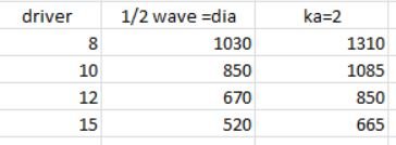
I've heard two different rules of thumb for when a driver leaves piston mode, and turns to breakup mode.
First is when driver diameter = 1/2 wavelength.
And second is when ka = 2. (ka being circumference/wavelength)
Both of these use dimensions not counting the surround.
Does this matter to folks?
Below is a quick chart showing the frequencies the two rules of thumb give for a few driver sizes. I used typical sd's for the given driver sizes, to get diameters for the calculations.
Attachments
I mentioned that already, once the wavelength is bigger than the opening whether woofer or horn, it looses directivity.
The dance between those specs of the woofer and horn, is how you should match polars, unless things are complicated somehow, like the banding issue for non circular horns, or other freq curve anonmolies for example. Circular horns makes it easy in that you can easily predict the behavior based on mouth diameter.
The dance between those specs of the woofer and horn, is how you should match polars, unless things are complicated somehow, like the banding issue for non circular horns, or other freq curve anonmolies for example. Circular horns makes it easy in that you can easily predict the behavior based on mouth diameter.
Last edited:
I also built a 90x60 waveguide. I found it was larger than a 90 degree axisymmetrical, when done properly (not with a flat front mounting), and it was very difficult to build.
All I got was a few dB off the ceiling. I can do the same thing with a cloud.
I completely concur.
I mentioned that already, once the wavelength is bigger than the opening whether woofer or horn, it looses directivity.
This isn't even close to being true. A good waveguide can control directivity well past its wavelength width. Maybe even 10x this frequency. I don't know where you got this idea, but it is not correct.
One thing that keeps bugging me when we are looking at matching directivity between cone and horn, is shouldn't we also be considering the pistonic range of the cone?
I've heard two different rules of thumb for when a driver leaves piston mode, and turns to breakup mode.
First is when driver diameter = 1/2 wavelength.
And second is when ka = 2. (ka being circumference/wavelength)
Both of these use dimensions not counting the surround.
Does this matter to folks?
Except that a real woofer is wider in directivity than a flat piston, I have to say that this "matters" greatly to me. The response of a woofer at its upper range of operation usually differs significantly from theory. That is why I contend that one must not actually measure this response, but also tailor the X-over to what one actually has in practice. Theory works great a great deal of the time, but you have to know when a (simplified) theory works and when it doesn't. For examples and rough calculation the piston model works OK, but for real world precision design, it is well off the mark.
Last edited:
"That is why I contend that one must not only measure this response, but also tailor the X-over to what one actually has in practice"
Hi, I changed the quote per your correction.
May I ask what you specifically mean by 'tailor the crossover to what one actually has in practice'?
Hi, I changed the quote per your correction.
May I ask what you specifically mean by 'tailor the crossover to what one actually has in practice'?
I completely concur.
This isn't even close to being true. A good waveguide can control directivity well past its wavelength width. Maybe even 10x this frequency. I don't know where you got this idea, but it is not correct.
Hi Gedlee, I accepted it to be true because the polars I’ve seen reflect. I didn’t know that was possible for a horn to have directivity at a wavelength larger than the diameter of its opening, can you provide polar charts/graphs to illustrate to the thread, please and thank you.
- Home
- Loudspeakers
- Multi-Way
- Is it possible to cover the whole spectrum, high SPL, low distortion with a 2-way?