Instead would it be better to establish the wavefront at all frequencies in a waveguide by making it large enough, then do something else, like turning the edge diffraction into entropy so it dissipates.
How does one do that?
It is the need for smooth termination and I suppose that holds for every horn. There should not be an edge, IMO. Then we can talk about the degree of edginess. Curve such as clothoid offers virtually none - you won't find any order of "edge" there. There will still be a mismatch of curvatures at a (flat) baffle junction however. Ideally the baffle would match curvature around the horn as well, although I'm still not sure that unbaffled but rolled-back horn would be better. At least for an infinite baffle this final curvature mismatch doesn't seem to make much trouble. "Inside" the horn it will be much more important.
Agreed.
I'm not sure I completely follow but once the mouth is big enough the only thing you care about is to ensure a smooth termination to mitigate further diffraction.
I didn't follow this either.
I suppose, yes.
I think it should also be about how. If the wavefront doesn't "let go" of the walls then it can widen.
Since there is no natural termination for conical style horns, any attempt is already an independent mission.
One cannot "allow" or "disallow" a wavefront to "follow" a curve. The wavefront does what the wave equation says it must do - you cannot change that. The wavefront will not follow a curve outwards and because of that diffraction is created at the edge of the wavefront to compensate for the wavefronts inability to follow the curve. The slower this is done the less diffraction.I'm not suggesting a simple radius termination, just that the wavefront not be allowed to "follow" the curve around.
There is going to be the same amount of diffraction on the whole. 'Minimising' could only mean 'spreading'. I think this is important.
The whole incorrect idea of Webster based horns is that we can force the wavefronts to follow any defined curve. It doesn't work like that. We have to find that curve or set of curves that best fit what the wavefront has to do and what we want it to do. That is exactly the point of view that led me to the OS contour. It meets this criteria, at least within the device, but if we want to terminate it then we have another problem which has to be dealt with and thuis a second curve to deal with the mouth.
Beneficial diffraction occurs gradually in the throat of an OS horn.
WHG
This is true, but I am unclear why it is beneficial. Below a modes cutoff this diffractions does not propagate, but above any modes cutin, this internal diffraction becomes a Higher order mode which does propagate. HOMs are not beneficial.
The LeCleach horn is a source of constant diffraction. Wavefront simulations appear to show diffracted energy continuing to reconstruct the wavefront to match the ever widening horn. Although distorted, it will reach around the mouth rollback.One cannot "allow" or "disallow" a wavefront to "follow" a curve.
Subjectively these sound clean, but I have not succeeded in having them close to a room wall.
I've been hanging on to this question for a while based on things I've read (and maybe inferred from that), but if I'm not mistaken, spreading in space gives an exponential reduction in pressure of the diffracted energy, and the spreading in time could mean some cancelled energy if the circumstances are right.How does one do that? (like turning the edge diffraction into entropy so it dissipates)
LF waves will do this, but HFs will not. The walls of a LeCleach horn will cause the wavefront to diffract to fill the space that is left by the walls receding faster than the wave equation will allow. At LFs this is effect, but as the frequency goes up this "filling" cannot occur which is why the wavefront leaves the walls and why this type of horn beams.The LeCleach horn is a source of constant diffraction. Wavefront simulations appear to show diffracted energy continuing to reconstruct the wavefront to match the ever widening horn. Although distorted, it will reach around the mouth rollback.
I've been hanging on to this question for a while based on things I've read (and maybe inferred from that), but if I'm not mistaken, spreading in space gives an exponential reduction in pressure of the diffracted energy, and the spreading in time could mean some cancelled energy if the circumstances are right.
This question is not possed in a way that I can answer. If "spreading in space" means free space, then there is no "diffraction" for an "exponential reduction in pressure" to occur. And "spreading in time" is also unclear to me, unless you mean HOMs which are spread in time, but don't happen in free space.
It's all about what the walls are doing and why I contend that it is not the rate of change of area, such as in Webster's equation, that matters, only the shape of the walls. Rate of change of area does not explain how waveguides work, but rate of change of the boundary does.
No, but they have never made any sense to me. I believe that they were an attempt to make the plug less expansive as good phase plugs require several parts and radial ones can be molded in a single piece. Few companies have adapted the idea, so I figure there must be a reason for that.
There is something of which I am still unsure what is causing it: Where does the waistbanding effect of waveguides and horns come from ? Is it caused by a ring-shaped (or whatever the mouth shape of the device is) virtual secondary sound-source caused by diffraction at the mouth ?
Regards
Charles
Regards
Charles
According to B. Kolbrek:
“waist-banding” effect, in which the horn looses energy out to the sides in the upper midrange.
In this thread Wayne Parham explains the phenomenon illustrated with lots of polars.
“waist-banding” effect, in which the horn looses energy out to the sides in the upper midrange.
In this thread Wayne Parham explains the phenomenon illustrated with lots of polars.
Last edited:
Danley Pure Groove impression Part II
Room 2
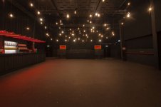
The second room wasn't used for the party and mostly blocked, apart from a passageway to the smoking area. This passage is the space between the Pure Grooves and the bar, visible in the attached picture.
Background music was being played through the SH96HOs, at a level many people would consider to be loud at home. Subs were switched off.
I had the opportunity to listen in the nearfeald (2-5m) to either one of the SH96HOs. There wasn't enough space in front of the Danleys for proper stereo.
"The SH96HO is a 3-way loudspeaker design housing 4 x 15” LF drivers, 6 x 4” MF drivers and 1 x 1.4” exit HF compression driver, all mounted within a 45” x 26” horn."
Ivan Beaver of Danley Sound Labs:
"THE "weak point" on the SH96 is the HF driver. The SH96HO is the same cabinet, but with a coax HF (as used in a couple of the Jericho products), a different crossover and switching options on the rear panel."
I suspect the Danleys were either high-passed somewhere in the lower midrange, because the bass seemed to be missing in action.
It's in the midrange where most of the music is and in this respect the SH96HO didn't dissapoint.
The 1.4" in the SH96HO is a BMS Coaxial, which essentially makes it a 4-way loudspeaker.
Separately and up close, these indeed resemble giant headphones, even more than I expected. There's a certain 'cuppy-ness', which was probably emphasized by the lack of low frequencies. This isn't surprising given the size of the horn, but it's more obvious compared to the Jerichos.
As with the Jerichos, there's no denying the point-source nature. From about 5 meters away, I walked towards the mouth without noticable differences in loudness or coherence. This is the special treat of synergies. Horizontal coverage is identical to the Jerichos and subsequently the impression off-axis is similar.
The mids and highs sounded very clear and highly detailed, while at the same time quite smooth. I guess the SH96HOs have a slight edge over the Jerichos as regards resolution, imaging and coherence.
However, I would definitely like to listen more extensively to SH96s and the smaller Danleys, before I decide to build a pair of synergies or MEHs.
Here's a video of a pair SH96HOs fullrange (without subs)
A case study by Merlijn van Veen
On a sidenote:
Originally Danley used FaitalPro HF14ATs for the SH96. These were replaced by the B&C DE880-8 in the summer of 2015.
The Faital HF14 and HF20AT are praised for their SQ, but apparantly the diaphragms are quite delicate and prone to failure.
It's therefore not surprising Faital seized production of both models.
Room 2
The second room wasn't used for the party and mostly blocked, apart from a passageway to the smoking area. This passage is the space between the Pure Grooves and the bar, visible in the attached picture.
Background music was being played through the SH96HOs, at a level many people would consider to be loud at home. Subs were switched off.
I had the opportunity to listen in the nearfeald (2-5m) to either one of the SH96HOs. There wasn't enough space in front of the Danleys for proper stereo.
"The SH96HO is a 3-way loudspeaker design housing 4 x 15” LF drivers, 6 x 4” MF drivers and 1 x 1.4” exit HF compression driver, all mounted within a 45” x 26” horn."
Ivan Beaver of Danley Sound Labs:
"THE "weak point" on the SH96 is the HF driver. The SH96HO is the same cabinet, but with a coax HF (as used in a couple of the Jericho products), a different crossover and switching options on the rear panel."
I suspect the Danleys were either high-passed somewhere in the lower midrange, because the bass seemed to be missing in action.
It's in the midrange where most of the music is and in this respect the SH96HO didn't dissapoint.
The 1.4" in the SH96HO is a BMS Coaxial, which essentially makes it a 4-way loudspeaker.
Separately and up close, these indeed resemble giant headphones, even more than I expected. There's a certain 'cuppy-ness', which was probably emphasized by the lack of low frequencies. This isn't surprising given the size of the horn, but it's more obvious compared to the Jerichos.
As with the Jerichos, there's no denying the point-source nature. From about 5 meters away, I walked towards the mouth without noticable differences in loudness or coherence. This is the special treat of synergies. Horizontal coverage is identical to the Jerichos and subsequently the impression off-axis is similar.
The mids and highs sounded very clear and highly detailed, while at the same time quite smooth. I guess the SH96HOs have a slight edge over the Jerichos as regards resolution, imaging and coherence.
However, I would definitely like to listen more extensively to SH96s and the smaller Danleys, before I decide to build a pair of synergies or MEHs.
Here's a video of a pair SH96HOs fullrange (without subs)
A case study by Merlijn van Veen
On a sidenote:
Originally Danley used FaitalPro HF14ATs for the SH96. These were replaced by the B&C DE880-8 in the summer of 2015.
The Faital HF14 and HF20AT are praised for their SQ, but apparantly the diaphragms are quite delicate and prone to failure.
It's therefore not surprising Faital seized production of both models.
Attachments
Last edited:
That’s why I’m here, for the learning. Sounds like youre suggesting that AE isn’t ideal for a subwoofer? When I first suggested the 18h+ for the sub I didn’t receive any negative commentary...until now
The WB of this unit is very large thanks to a thin an flexible cone, this kind of radiator is highly ctiticizable for the low end accuracy, particuliarly with a small VC.
The old classics are much better (TAD, ALTEC, JBL...)
There is something of which I am still unsure what is causing it: Where does the waistbanding effect of waveguides and horns come from ? Is it caused by a ring-shaped (or whatever the mouth shape of the device is) virtual secondary sound-source caused by diffraction at the mouth ?
Regards
Charles
That's correct.
The old classics are much better (TAD, ALTEC, JBL...)
It is hard to beat the highly refined capabilities of the classic 15" woofer designs. It has withstood the test-of-time and come through with flying colors. To me, the 15" is the sweat spot for a great loudspeaker. The 18's just don't seem to be as good in general, and 12s don't have enough directivity for a good polar match to a high DI waveguide.
It is hard to beat the highly refined capabilities of the classic 15" woofer designs. It has withstood the test-of-time and come through with flying colors. To me, the 15" is the sweat spot for a great loudspeaker. The 18's just don't seem to be as good in general, and 12s don't have enough directivity for a good polar match to a high DI waveguide.
It is a very unusual application but it should help a little i think.
Blue 24in 100Gr paper straight cone 60° free air dipole at 30cm
Red 24in 200Gr paper straight cone 60° free air dipole at 30cm

PS : REW traces colors are beautifull

Potpourii
WHG
Early morning errant word choice. So what?If you intended just that, then I don't understand why you called it an inflection point.
Using an unifying, but flexible fairness curve, should expand the investigatory domain and reduce design iteration cycle times. Will this methodology deliver an optimized acoustic horn design? As demonstrated by the article provided earlier, the answer to this question is a most likely yes.Curvatures of both segments will match at this junction, i.e. it should be smooth enough. There's no need to go for splines as I have it already working as it is. Is it possible to do it a bit differently? Of course it is. Will it be any noticeably better? Please show me that.
I am not in the horn design and manufacturing business at the moment. If I were, you would see a lot of C-Bézier horns in the marketplace and details concerning the design methodology used, would remain undisclosed.- It was year 2013. So where are all the waveguides terminated by Euler spiral segment?
WHG
Last edited:
Agreed.
>snip<
This is true, but I am unclear why it is beneficial. Below a modes cutoff this diffractions does not propagate, but above any modes cutin, this internal diffraction becomes a Higher order mode which does propagate. HOMs are not beneficial.
The benefit is provided by the curvature decline. WHG
The benefit is provided by the curvature decline. WHG
Sorry Bill, I don't follow what you mean.
It is a very unusual application but it should help a little i think.
Blue 24in 100Gr paper straight cone 60° free air dipole at 30cm
Red 24in 200Gr paper straight cone 60° free air dipole at 30cm
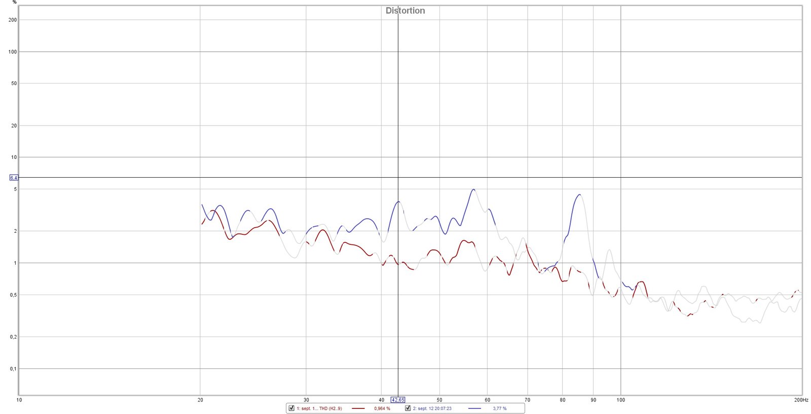
PS : REW traces colors are beautifull
24" with 100g cone, must be a vintage driver?
The 200g cone is the same driver with added mass?
I woudn't say I share your conclusion. In the paper you referenced they optimized for two fixed control points on the contour. How would you know if the optimum found is a global one, no matter where and how many points you would choose? It's actually still quite limited result and in principle will allways be - it would take a heck of a time to go through all possibilities.Using an unifying, but flexible fairness curve, should expand the investigatory domain and reduce design iteration cycle times. Will this methodology deliver an optimized acoustic horn design? As demonstrated by the article provided earlier, the answer to this question is a most likely yes.
The most time consuming part is the actual simulation run, not the way how you get the contours under test. I'm quite willing to incorporate an import function of an arbitrary countour curve (as a text file) to my program that generates a BEM project that can be run on a readily available freeware simulator. Anyone could easily test their favourite profile. That would be a nice contest...
That's quite a bold statement.I am not in the horn design and manufacturing business at the moment. If I were, you would see a lot of C-Bézier horns in the marketplace and details concerning the design methodology used, would remain undisclosed.
Last edited:
Sorry Bill, I don't follow what you mean.
Compared to other horns, OS horns have a throat profile of declining curvature, the rest have increasing curvature throughout their length; or none at all, as in the case of the (asymptotic) conical horn. Other means of wave spreading include sharp diffraction edges, 'speed bumps' (JBL), and dispersive acoustic lenses and reflectors which produce all sorts of (non-beneficial) response anomalies. WHG
Last edited:
- Home
- Loudspeakers
- Multi-Way
- Is it possible to cover the whole spectrum, high SPL, low distortion with a 2-way?