I was just looking at ZXPC's 17x11 horn. Any view on this horn vs. ZXPC's 18x10 horn? Btw, my CD is Renkus 3301.This JBL 2386 clone can be used from about 500-600Hz, depending on the driver.
View attachment 1059066
It's used by DonVK in this project.
From your own thread:
What cap (brand) did you use?
35uF is quite a high value and I definitely wouldn't use just any no-label cheap electrolytic cap in this case.
Diaphragms for your drivers are virtually unobtainable, so better be careful.
Check both this and the Klipsch forum and search for ZXPC.
Just played some hi-res classical violin solo music (i.e., no deep bass at all) without any crossover. The drivers sounded tremendous. Then I added a 35uf in series to filter out ~600hz and below. I FELT that the sound became a bit "tamed" -- no as fast paced or transparent as before.
Obviously if having no crossover will cause damage to the drivers, I will certainly add one.
What cap (brand) did you use?
35uF is quite a high value and I definitely wouldn't use just any no-label cheap electrolytic cap in this case.
Diaphragms for your drivers are virtually unobtainable, so better be careful.
I was just looking at ZXPC's 17x11 horn. Any view on this horn vs. ZXPC's 18x10 horn? Btw, my CD is Renkus 3301.
Check both this and the Klipsch forum and search for ZXPC.
Last edited:
Thanks! You are actually 100% right. The pair of Renkus 3301 I mentioned in that post died when I accidently dropped them on my concrete basement floor maybe two years ago (both bodies cracked). I then sold the ZXPC horns at the time.From your own thread:
What cap (brand) did you use?
35uF is quite a high value and I definitely wouldn't use just any no-label cheap electrolytic cap in this case.
Diaphragms for your drivers are virtually unobtainable, so better be careful.
Check both this and the Klipsch forum and search for ZXPC.
I do not recall exactly what caps I used, but they were definitely the film type, as I was heavily invested in building that system at the time.
Now I have just obtained a new pair of Renkus 3301 and are re-visiting the CD/Horn + bass two-way system. It appears that ZXPC, whether 17x11 or 18X10, is still the go-to, easily-obtainable source, although for a moment I had some hope in the 15" round horn.
Yep, I see where you coming from.

Aluminum is the preferred diaphragm material of the 'the gods' (Lansing, Vitavox, WE).
I should have bought the drivers containing these diaphragms (Aluminium + Titanium surround) 20 years ago, when they were occasionally offered at scrapyard prices:

Today, the drivers with this diaphragm represent a decent alternative:

Aluminum is the preferred diaphragm material of the 'the gods' (Lansing, Vitavox, WE).
I should have bought the drivers containing these diaphragms (Aluminium + Titanium surround) 20 years ago, when they were occasionally offered at scrapyard prices:
Today, the drivers with this diaphragm represent a decent alternative:
Im going to get some outside measurements tomorrow... I dont have a mic stand so I'll have to rig something up...It's a long thread. Did you post the specs for those horns ?
Putting the mic body into one end of a long section of plastic pipe from a DIY store is an option. Make sure it's rigid enough and clamp the other end to something far enough away that you can gate out the reflection.
A big bonus point is that this setup has fewer HF reflections in the data compared to a typical mic stand and clip.
You also don't have to aim the horn up to the sky. Put the horn on a fold-out painter's table - the kind made of aluminium extrusion - with some thick blankets underneath. You'll probably be able to get more distance from the nearest boundary this way, and with some floor markings as guidance, you can rotate the makeshift platform for polar measurements.
I've seen good data for professional speakers produced this way, with sensible windowing / splicing of LF measurements.
Hi, could you please provide a small sketch how the mic should be mounted in the pipe and how the measurement setup would be with this arrangement? Thanks.Putting the mic body into one end of a long section of plastic pipe from a DIY store is an option. Make sure it's rigid enough and clamp the other end to something far enough away that you can gate out the reflection.
...
Like shown here?Hi, could you please provide a small sketch how the mic should be mounted in the pipe and how the measurement setup would be with this arrangement? Thanks.
http://www.troelsgravesen.dk/measurements.htm
Ok experienced system analyzers...
I just measured 1meter, 200hz, 107db, 8% 2nd order thd...
I know we discussed in detail the idea of 20-30db of headroom...I've trying to everything within xmax at 115db... eventually came to the conclusion that 115db on the z scale is crazy loud... and that only bass would ever get that loud in a home system.....
I remember @mark100 and @weltersys commenting and a "fork drop" at 1m hitting 115db...
What Im trying figure out; is the above, enough headroom to cross over at 200hz....
Same levels.... I put the mic on the exit, and found a peak in 2nd order thd at 80hz of 12%...
No sound of diaphragm hitting anything at least that I can tell....
200hz bessel 12db.... inside (the house) derived Eq correction...

300hz 12db bessel and better, outside, eq correction...

I limited volts to 3 @ 1000hz and tested just under voltage attenuator....

last 2 mdat files in attachments....everything at 1meter
@DonVK
I just measured 1meter, 200hz, 107db, 8% 2nd order thd...
I know we discussed in detail the idea of 20-30db of headroom...I've trying to everything within xmax at 115db... eventually came to the conclusion that 115db on the z scale is crazy loud... and that only bass would ever get that loud in a home system.....
I remember @mark100 and @weltersys commenting and a "fork drop" at 1m hitting 115db...
What Im trying figure out; is the above, enough headroom to cross over at 200hz....
Same levels.... I put the mic on the exit, and found a peak in 2nd order thd at 80hz of 12%...
No sound of diaphragm hitting anything at least that I can tell....
200hz bessel 12db.... inside (the house) derived Eq correction...
300hz 12db bessel and better, outside, eq correction...
I limited volts to 3 @ 1000hz and tested just under voltage attenuator....
last 2 mdat files in attachments....everything at 1meter
@DonVK
Attachments
Yes, a fork dropping on a plate will produce around 115dB, hands clapping at one meter, around 125dB peak. The short duration of those peaks does not sound near as loud as a sustained tone of the same frequency range.I just measured 1meter, 200hz, 107db, 8% 2nd order thd...
I remember @mark100 and @weltersys commenting and a "fork drop" at 1m hitting 115db...
What Im trying figure out; is the above, enough headroom to cross over at 200hz....
I limited volts to 3 @ 1000hz and tested just under voltage attenuator....
In your "outside horn May 30, 2022 12:05PM" measurement (at 3volts?) THD has reached 102% at 100Hz. The previous test "300hz 12db bessel and better" has distortion about -8dB less, indicating the shallow crossover at 300Hz is still too low if you prefer undistorted output, and protection of the AXI2050 diaphragm when used for peaks exceeding one watt or so.
Art
It looks like you didn't use the acoustic timing reference option with your UMIK-1, so some distortion in both shared sets of IR data is likely due to timing errors. From the REW help file/manual (which is a great read):
The default Windows 'helpful' microphone echo cancellation setting is worth checking, especially if you're using Windows 10 or 11:
You've not named your traces or added notes, so try to do that in future. It really helps others understand if the data is valid, and what it's showing. Others includes your future self!
Good things to add in notes are:
That aside, there is considerably more noise present in the second (green) trace. The noise floor rises by around 15 dB between measurements, and that means your data isn't really trustworthy below 150Hz due to the SNR falling below 20dB:

Did a car go by or something? It also looks like the mic was closer for this second measurement, although I'm not familiar with how the UMIK-1 in REW works out the calculation of distance when there's no timing reference...
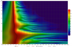
Wavelet analysis of your data also supports what Art has already said. I prefer to see a wavelet plot (called Spectrogram in REW) with the time axis in cycles and without any prior processing of the device, as it is easier to quickly assess visually if the resonance is overly long, or caused by diffraction.
REW doesn't offer that function, but you can still see where the driver is becoming unloaded below 300Hz on both sets of data.
Watch out with the scale! REW seems to keep the colour legend in absolute dB values, despite this plot being normalised to the peak magnitude at each frequency. Orange is -6dB from peak value, green is -12dB:

Oh, and you appear to have wired the driver with inverse polarity")
Settings for the measurement method are on the right hand side. Length controls the length of the sweep, specifying the number of samples in the sequence. The default is 256k which works well for most purposes. Dividing the number of samples by the interface's sample rate gives the sweep duration in seconds, shown to the right. The overall duration includes silent periods before and after the sweep. If the input and output are on the same device and so share a common clock longer sweeps will provide higher signal-to-noise ratio (S/N) in the measurements. Long sweeps may be problematic when the input and output are on different devices, such as when using a USB mic, as their sample clock rates will differ. Over a long sweep a significant difference in clock rates could cause severe distortions in the shape of the impulse response and affect the phase response. This can be corrected by using the acoustic timing reference and the Analysis option to Adjust clock with acoustic ref or, if a loopback connection is being used as a timing reference, the Analysis option to Adjust clock with loopback.
The default Windows 'helpful' microphone echo cancellation setting is worth checking, especially if you're using Windows 10 or 11:
There seems to be a growing trend for Windows laptops and PCs to apply noise cancellation processing to stereo microphone inputs, suppressing the content that is common to both channels. With USB microphones like the UMIK-1 the signal is the same on both channels, so it is all common content, and may be heavily suppressed. If there are user controls for noise cancelling processing on inputs make sure they are off for the measurement input. Processing for an input can be turned off by going to the Windows Sound Settings, then selecting Sound Control Panel under Related Settings. Select the microphone to be used from the Recording tab then click the Properties button and select the Advanced tab. If there is an Enable audio enhancements box make sure it is not checked.
You've not named your traces or added notes, so try to do that in future. It really helps others understand if the data is valid, and what it's showing. Others includes your future self!
Good things to add in notes are:
- Signal path, including devices, gain settings/knob positions, pads etc
- Any DSP or electronic filtering
- Mic position, including distance, angle and capsule orientation
That aside, there is considerably more noise present in the second (green) trace. The noise floor rises by around 15 dB between measurements, and that means your data isn't really trustworthy below 150Hz due to the SNR falling below 20dB:
Did a car go by or something? It also looks like the mic was closer for this second measurement, although I'm not familiar with how the UMIK-1 in REW works out the calculation of distance when there's no timing reference...
Wavelet analysis of your data also supports what Art has already said. I prefer to see a wavelet plot (called Spectrogram in REW) with the time axis in cycles and without any prior processing of the device, as it is easier to quickly assess visually if the resonance is overly long, or caused by diffraction.
REW doesn't offer that function, but you can still see where the driver is becoming unloaded below 300Hz on both sets of data.
Watch out with the scale! REW seems to keep the colour legend in absolute dB values, despite this plot being normalised to the peak magnitude at each frequency. Orange is -6dB from peak value, green is -12dB:
Oh, and you appear to have wired the driver with inverse polarity
Attachments
Last edited:
Heres the thing...... In a horn, low frequency production will be supported by the Horn.....in the areas where there is no loading, you'd think that the driver oul have the potential to unload, as in, over excursion.... when I put the microphone, on the exit....2nd order Thd is much lower...maybe 3-4%......Yes, a fork dropping on a plate will produce around 115dB, hands clapping at one meter, around 125dB peak. The short duration of those peaks does not sound near as loud as a sustained tone of the same frequency range.
View attachment 1059630
In your "outside horn May 30, 2022 12:05PM" measurement (at 3volts?) THD has reached 102% at 100Hz. The previous test "300hz 12db bessel and better" has distortion about -8dB less, indicating the shallow crossover at 300Hz is still too low if you prefer undistorted output, and protection of the AXI2050 diaphragm when used for peaks exceeding one watt or so.
Art
Doesn't that suggest that the driver is not over extruding????
I'd think that in this situation, 2nd order thd will always increase as we move the microphone away from the the horn....the higher frequency of the distortion has a higher directivity, thus will dominate as the mic moves away from the horn, in particular because of the unique way a horn produces its LF section.
In the areas where there is no loading, does it not make sense to check for distortion, at the Driver exit? since the horn is no longer apart of system at this point?
is my Hornresp sim using a 2nd order bessel at 300hz untrustworthy?
To recap my thoughts....
I am suggesting that the Diaphragm isn't in danger....rather, Distortion is high due to higher order harmonics loading better than the fundamental as well as having higher directivity....
at 100hz we are down ~50db from the areas that are fully loaded and to be neutrally voiced.

wouldn't that make 100hz from the 15" more dominate and thus lower 2nd order thd?
This is pretty close if not, a FR of the transients.... Can we call it a transient FR?
when I put the mic on the driver exit, I get ~1-2% 2nd order thd......for the, what I believe, is the same output settings that created the above...
So can I conclude that, the driver is not over excurting?
And after confirming that... thd at listening point can be judged after mating with woofer...or excluded in areas that are below -25db for example...
If anything I am saying makes any sense....then at a <95db listening ....there should room for peaks still. 100hz being at 45db average.... not to mention everything below about 150hz will be woofer dependent.
As I swept lower, I did find areas that 2nd order as 12%....Maybe suggesting a 24db at 300hz instead of 12? According to Hornresp....with the 300hz 2nd order high pass....I am no wheres near xlim at very high levels.... looking at the above measurement I bet the harmonic below cutoff could be the culprit and that they could be eq'd out.
I am suggesting that the Diaphragm isn't in danger....rather, Distortion is high due to higher order harmonics loading better than the fundamental as well as having higher directivity....
at 100hz we are down ~50db from the areas that are fully loaded and to be neutrally voiced.
wouldn't that make 100hz from the 15" more dominate and thus lower 2nd order thd?
This is pretty close if not, a FR of the transients.... Can we call it a transient FR?
when I put the mic on the driver exit, I get ~1-2% 2nd order thd......for the, what I believe, is the same output settings that created the above...
So can I conclude that, the driver is not over excurting?
And after confirming that... thd at listening point can be judged after mating with woofer...or excluded in areas that are below -25db for example...
If anything I am saying makes any sense....then at a <95db listening ....there should room for peaks still. 100hz being at 45db average.... not to mention everything below about 150hz will be woofer dependent.
As I swept lower, I did find areas that 2nd order as 12%....Maybe suggesting a 24db at 300hz instead of 12? According to Hornresp....with the 300hz 2nd order high pass....I am no wheres near xlim at very high levels.... looking at the above measurement I bet the harmonic below cutoff could be the culprit and that they could be eq'd out.
Last edited:
As already stated , it would be worthwhile to slowdown and understand how to measure using REW.
P.S. I'm away for the next few days but there are plenty of people here that can help you with the details. Contrats on getting the horns home,
- is all the Windows sound processing off? (can be checked with line level loopback,, are you using laptop soundcard?)
- use the IR window (gating), sound travels 3ms / m so for a 6ms IR gate, nearest object is at least 1m away ( further is better)
- use acoustic timing reference for the UMIK, and use the "estimate and remove IR delay"
- use lower levels (80-90dB) initially while you're getting the setup working
P.S. I'm away for the next few days but there are plenty of people here that can help you with the details. Contrats on getting the horns home,
Sometimes it's good to follow a good example.

Bjørn Kolbrek uses the Axi2050 from 300 Hz with his Hyperbolic-Exponential horn (T=0).
Length was originally 95.5cm, but is now probably closer to 80cm due to a new throat adapter. The mouth is 65 x 65cm.
Given the size and the profile of your horn, a crossover somewhere between 300-400Hz seems reasonable.
Oh, and the original throat transition is similar to your horn:
Last edited:
You are in the acoustic near-field at the mouth, so the signal to noise ratio is much higher.Heres the thing...... In a horn, low frequency production will be supported by the Horn.....in the areas where there is no loading, you'd think that the driver oul have the potential to unload, as in, over excursion.... when I put the microphone, on the exit....2nd order Thd is much lower...maybe 3-4%......
The best way to find out empirically if the driver is reaching the excursion limit is to simultaneously measure the electrical impedance and magnitude response. Start at a low drive level, such as the scaled 2.83V @ 1m equivalent voltage for your measurement distance from the mouth, and increase it in 3dB steps until a significant deviation of response shape is observed in any of the responses.
This is one reason that data measured in the acoustic near-field need to be carefully considered against other data sets.I'd think that in this situation, 2nd order thd will always increase as we move the microphone away from the the horn....the higher frequency of the distortion has a higher directivity, thus will dominate as the mic moves away from the horn, in particular because of the unique way a horn produces its LF section.
As I said the other day, you'd be best off measuring the horns at your expected listening distance for the most part, given that you'll struggle to get into the far-field. I presume this will be more than 1 metre?
This would also have the benefit of pushing the reflection from the ground plane behind the horn lower down in frequency.
You might also want to move your 'table' for the other kit farther away for the same reason.
Oh, and document your signal path!
What's your output interface?
What amp?
How is it connected? Use balanced interconnects to avoid noise from your laptop power supply etc.
What reference output voltage?
Just use a DMM and 100Hz sine wave from REW's signal generator to measure that at the output terminals of the amplifier. Then you can calculate the increase in voltage when you increase the gain of the measurement signal in REW or on your audio interface.
Yes. Professional horn development often uses a prototype that has a small opening at the throat to allow a microphone capsule to be inserted at that position, as well as monitoring the driving point impedance & voltage/current. You'll see a deviation in (good) electrical terminal measurements from diaphragm issues too.In the areas where there is no loading, does it not make sense to check for distortion, at the Driver exit? since the horn is no longer apart of system at this point?
As ever, you need a good reference point to determine when things are 'going bad'. Get data for low-level signals, without any prior filtering - including limiting - and use this as your baseline.
That way you can begin to separate the effects of various acoustic and electrical components or behaviours.
As far as I'm aware, you can't use the typical T/S parameters for a compression driver.is my Hornresp sim using a 2nd order bessel at 300hz untrustworthy?
You'd get clearer results for the horn behaviour alone if you can use a 'perfect' transducer such as a plane wave source, even in a lumped element model.
If you want to simply observe the shape & effect of a Bessel or other DSP filter on a flat response, then VituixCAD is good for that.
If you have a measurement of the driver & horn without filtering at a reference distance then you'll find it much easier to see if the filtering is improving things at a given frequency region.
- Home
- Loudspeakers
- Multi-Way
- Is it possible to cover the whole spectrum, high SPL, low distortion with a 2-way?