Good point, these were some images I could quickly find to try and save a few thousand words, good images for high passes eluded me, I tried flipping them in Paint but it seemed more confusingJust want to mention that those figure are for a LP filter and would be reversed for a HP. But thanks.
")
Attachments
Here's dcx464/me464 lower section raw on-ax.
"Phase" graph is group delay. Someday the Smaart guys will fix the label when toggling from phase.
View attachment 987137
Good luck with your quest. I ask you count me out for any more measurements towards it though....it seems pointless to me.
i'm simply after how to make better sound than i've ever heard before, which for me means keeping my eye on the 'pragmatic big picture ball'.
How far away was the mic for this measurement?
Can you re-post that pic without the SMOOTHING So we can see the RAW response
You spoke of the "bigger picture".... I think you would like to visit burst decay and avoid the same area where GD gets too high, which is also the area with excess decay
Last edited:
Camplo,
The terms are not ambiguous- Fc (Frequency of horn Cutoff) is used for exponential type horns, Fb (Frequency of Box tuning) for Helmholtz resonators, "bass-reflex" enclosures.
The use of Fc regarding conical expansion "waveguides" is not of much use since they exhibit no abrupt "cutoff" frequency, nor is using a compression driver much below it's Fs on any horn or waveguide driven anywhere near peak power ratings, if the best sound quality is the goal.
Art
I just spent several minutes trying to figure out why I thought Fc was for sealed boxes and not conical expansion only to realize that it is ambiguous lol
Regarding your last statement, for domestic use we aren't going anywhere near peak power ratings...so playing below fs on a horn is applicable and dictated by excursion in which the horns loading will help alleviated...I know you know this already, just keeping it in the picture
Last edited:
I thought the connection to time to peak energy, was exactly that...group delay does not have a time domain equivalent that I know of.
Remember I posted the graphs next to each other and the trend lines where almost identical?
If there is truly a connection to the amplitude envelope, as I suspect and read about....I just realized that I should be able to record it and display the signal as such....I will try.
Good point, these were some images I could quickly find to try and save a few thousand words, good images for high passes eluded me, I tried flipping them in Paint but it seemed more confusing
Fluid
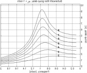
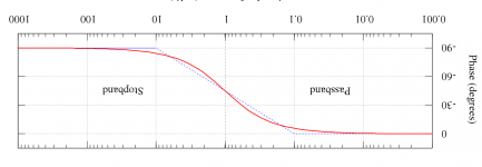
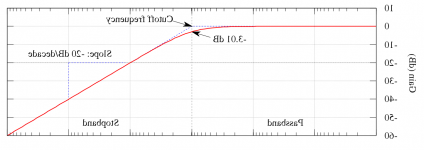
Unfortunately your pictures do only tell the truth when it comes to amplitude- and phase- response.
The group delay has the same lowpass-like shape for the high- and lowpass. This is because group delay is defined as the negative derivative of the phase response. And the phase response of high- and lowpass filters have the same kind of shape that is falling with rising frequency and asymptotally reaching a finite value at zero Hz and infinity. With the only difference that the phase response of a lowpass is zero at zero Hz and -90 degrees per order for frequencies approaching infinity while the highpass has +90 degrees of phase shift per order towards zero Hz falling towards zero at infinity.
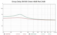
If the group delay of a high pass was like the one you showed then the design of multiway speakers with simple analog crossovers that can reproduce square waves would be a walk in the park.
Regards
Charles
I thought the connection to time to peak energy, was exactly that...
The point in time when the peak energy is leaving your speaker is not determined by the group-delay alone but also by the spectral content of the input test signal.
When you have a peaking group-delay but no content in the frequency range of the peak then that GD peak is meaningless for the outcome.
Same for group delay rising towards lower frequency. A speaker with a very low cutoff frequency will have higher group delay around its cutoff than one with a higher cutoff frequency. But the one with the lower cutoff frequency will most likely have less group-delay in the lower midrange.
Regards
Charles
Yes that was the point I was trying to make when I said they they were confusing when flipped. I should have left the flipped group delay out. I have been able to make my own graph now to show the high pass group delay correctly for a BW filter of 24 and 48dB to make it easier to see the group delay peaks. The main point being that group delay peaks around the cutoff -3dB point of a filter.Fluid
Unfortunately your pictures do only tell the truth when it comes to amplitude- and phase- response.
Attachments
the idea of crossing a horn over 2x above cutoff is Jean's philosophy wasnt it?
Maybe is was his philosophy, I don't know, but I find the idea rather ridiculous.
For horns with a clearly defined cutoff (such as an exponential or a Le Cléac'h horn), the generally accepted rule of thumb is 1.5 times the cutoff frequency. Paul Klipsch chose a value of 1.5 when designing his K-400 midrange horn (as used in the Klipschorn). The K-400 horn has a cutoff frequency of 270 Hz, and as the name suggests, is designed to be crossed-over at 400 Hz.
It would seem that Jean-Michel perhaps used a more conservative factor of 2 when designing his horns.
This is a measurement taken in the real-time two-channel mode of Smaart, using the default MTW frequency-dependent window, right?
Hi, correct.
My poor man's anechoic is outdoors, albeit in a noisy environment. Real-time temporal average of music with some background pink thrown in, let's me make non-annoying measurements, compared to averaging a bunch or IR sweeps.
Unfortunately, I don’t personally class that as a very accurate measurement procedure for the characterisation of absolute phase and by proxy, group delay. It is very easy, but Smaart in real-time mode can make speakers look much better than they really are. That's a side effect of the software's focus on getting 'actionable data' for alignment of multiple speakers at events. 1/6th octave smoothing doesn't help either!
I use Smaart to easily capture as you say, 'actionable data'.
If i've wanted to dig further, i normally go to REW or ARTA.
What do you use to capture 'absolute' phase?
I've heard TEF can, but have no experience with it or anything other than what I've mentioned.
As you know, unsmoothed data is what's captured. I probably made a mistake posting the group delay with 1/6 octave smoothing, but knowing the over-theorizing going on in this thread, that was what i was trying to avoid with a 'bigger picture' view.
At any rate, will repost with unsmoothed next.
If you use the IR mode, it is easier to post-process as needed, with less chance of introducing error into the data. I use Smaart a lot, but it's also good to know where it's limits lie - and why there are still plenty of awesome measurement platforms that offer non real-time measurements, with a wider variety of data processing as a result.
Yep. Have you used the recent Smaart 8.5 upgrade? Lot's of IR response improvements it seems.
For mag and phase traces, I've yet to find any benefit from the better data of non-real time IR captures (with REW or ARTA sweeps or Smaart's 'Pink Sweep').
Most of the time i end up tuning to spatial averages anyway, so I kinda reserve IR work for looking for time domain issues, after getting the best mag and phase tuning i can. Then re-circle to mag and phase.
Is their a better process in your opinion?
How far away was the mic for this measurement?
Can you re-post that pic without the SMOOTHING So we can see the RAW response
You spoke of the "bigger picture".... I think you would like to visit burst decay and avoid the same area where GD gets too high, which is also the area with excess decay
Hi camplo,
About 3m away.
Here's no smoothing.

And NO, i don't give a damn about burst decay, or area of excess decay, or etc etc.
I can see performance deteriorates the lower it goes. But we all know and expect that, right..
So I build a set of xovers through the range of measurement deterioration and go listen. That's what i give a damn about
Maybe you should should learn how to read and interpret the graphs you are asking for.
Everything I predicted has come true so far. Based off of electrical impedance to start.
Hi camplo,
About 3m away.
Here's no smoothing.
View attachment 987311
Dang it! I thought you'd know better than to include the room in the measurement. Basically a measurement at the mouth, vs 3m away...The cutoff is low enough to be within room interaction... wanted to see just horns response not horn plus room.
Last edited:
Dang it! I thought you'd know better than to include the room in the measurement. Basically a measurement at the mouth, vs 3m away...The cutoff is low enough to be within room interaction... wanted to see just horns response not horn plus room.
Haha...i always specify if it's an in-room measurement, to let reader beware.
Default is 3m outdoors, off my back deck which opens out to empty space nicely.
True enough, if you ever feel like the bother...a direct energy measurement can be taken without having to move your horn from its current location....just put the mic barely an inch away from the horn mouth, dead center and fire away =)
It gives you a clearer view of what your horn/driver is going.
It gives you a clearer view of what your horn/driver is going.
Measurements for horns should be taken in far-field conditions. So should any speaker, really. Taking near field measurements is only appropriate when they are manually convolved with a majority of far-field data.
Group delay is also derived from phase data, which is influenced by relative distance, reflections and the like.
All of the ‘mic’ type ABEC/Akabak observation types default to a far-field determination which is then compensated to produce the response at the designated measurement point. So it calculates the response at 10 metres, then adjusts the gain via inverse distance law to give the response at 0.1 metres, if that’s where you set the point position.
There’s a good reason for that. It’s also why anechoic rooms are qualified via inverse distance traversal methods, plotting the deviation from theoretical results for different angles and positions of source and receiver.
A good rule of thumb is to measure at 3 or 4x the diagonal distance of the baffle for the device under test.
Last edited:
back deck which opens out to empty space nicely.
Very nicely I would say. The view you have there is really something special.

That doesn't automatically mean - you cant or shouldn't ever take a direct energy measurement.
People take these types of measurements all the time, its just another way of viewing data, in this instance, its a good way to eliminate the room in the absence of an anechoic chamber.
People take these types of measurements all the time, its just another way of viewing data, in this instance, its a good way to eliminate the room in the absence of an anechoic chamber.
- Home
- Loudspeakers
- Multi-Way
- Is it possible to cover the whole spectrum, high SPL, low distortion with a 2-way?