You haven't seen my cabinets yet?! I guess you did join the convo later on....you better not leave either. Road construction workers have a very crude way of communicating, if you don't have thick skin, you might feel hurt out here...Hopefully Fluid can see through the details and that I really don't want anyone to leave the table....
Mark, if you ever get a chance, please post your unfiltered GD results...someone said that you cannot reverse engineer other aspects using the electrical impedance...I disagree.
Earl asked me what theory was I going on about....the idea of crossing a horn over 2x above cutoff is Jean's philosophy wasnt it?
The last theory I remember selling was first only a theory because I don't know...but definitely known. If you look back, I posted a bunch of hornresp graphs
Is it possible to cover the whole spectrum, high spl, low distortion with a 2-way?
My theory was regarding group delay and throat pressure...some post back I stated that I believe group delay caused from loading, more or less, is another way of saying "caused from pressure"....I stated that pressure causes the diaphragm to lag, inherently causing the group delay...sounds good. Might be wrong, not everyone, I trust to even actually know whats happening on that level or admit they dont know, Earl being a perspective I trust.
Paul, pics of my cabs are buried in this thread, Ill post a pic when I can...I have to return my td15m's cause they don't measure right....I have to come up with a way stand these horns...to which the large 150hz horns are being crafted somewhere in Germany currently
I have amps...the amps have dsp...
I think the biggest change was letting go of center to center spacing goals...everyone else says F it, I guess I joined the club. Mitchba has ears like I do...and he has a TMM 2 way which is the opposite of good center to center spacing...last time he spoke he mentioned hes been very happy with his system and that if he could have something change, He'd get a bigger horn....that was my walla moment, that basically directivity was the real prize.....How you get it...Doesnt matter so much...oversimplification of course....anyways, that was enough to get moving towards a purchase. I dont mind a small listening window, but I do care about a great looking impulse, less reflections gets you there. A large horn gets you less reflections....plus I can finally achieve 300hz with the Axi, the proper way (well above horn tuning) with such a large horn. So an ~32" wide elliptical tractrix it is lol. What ever I dont like, I'll sell it, except for the jbl 238(5/0)a...she stays. I have to eventually build a waveguide because if I have these various horns why wouldnt I compare them to the waveguide experience....
Earl asked me what theory was I going on about....the idea of crossing a horn over 2x above cutoff is Jean's philosophy wasnt it?
..
Maybe is was his philosophy, I don't know, but I find the idea rather ridiculous. My waveguide "cutoff" (1/2 power) is my HP filter.
My theory was regarding group delay and throat pressure...some post back I stated that I believe group delay caused from loading, more or less, is another way of saying "caused from pressure"....I stated that pressure causes the diaphragm to lag, inherently causing the group delay...sounds good. Might be wrong, not everyone, I trust to even actually know whats happening on that level or admit they dont know, Earl being a perspective I trust.
You appear to be talking about instantaneous pressure - at a moment in time. This is a misleading way of thinking about things because most of what we are talking about, group delay, etc., are based on system level responses as a whole and as such no instantaneous time point of view is going to be very inciteful.
In physics we usually start talking about things in time, forces, pressures and the like, and use Newton's equations for a solution. But as one develops more mathematical tools we find that the frequency domain is far far more effective. Virtually everything that we have talked about are frequency domain concepts and do not have good representations in time. For example, impedance is purely a frequency domain concept - there is no time domain equivalent. Delay in the time domain is phase in the frequency domain, but group delay does not have a time domain equivalent that I know of.
In essence, I would say that the idea above is not likely to be valid. But if you can express it in the frequency domain then maybe it might. But that would take some deep understanding of system theory, which I don't think that you have ....... yet!
Last edited:
I don't know if you are suggesting that my skin in thin. Nothing could be further from the truth if that is the case. You need to adapt your communication style to the audience you have before you, the law of the building site does not extend beyond it. I have developed a very small tolerance for time wasting nonsense and you exceeded my threshold.Road construction workers have a very crude way of communicating, if you don't have thick skin, you might feel hurt out here...Hopefully Fluid can see through the details and that I really don't want anyone to leave the table....
To get less reflections the termination at the mouth needs to be optimized and avoid sudden changes in curvature. A bigger horn may change when the reflections occur but it won't remove them if the termination is bad.I dont mind a small listening window, but I do care about a great looking impulse, less reflections gets you there. A large horn gets you less reflections....
it seems from a pragmatic point that conical cutoff is pretty much immaterial.
Hornresp does not show conical horn cutoff frequencies for that very reason
") .
.Just to complete the picture, infinite parabolic horns also have a theoretical cutoff, defined as the frequency at which k * xt = 0.268.
xt in this case is the distance from the apex of the parabola to the throat.
fc = 0.268 * c / (2 * Pi * xt)
Hornresp does not show parabolic horn cutoff frequencies either
.Cutoff in a conical is even more of a hopeless description than when applied to OS.
...well it seems from a pragmatic point that conical cutoff is pretty much immaterial.
Seems we agreeHornresp does not show conical horn cutoff frequencies for that very reason
Seems we agree
Almost
.It depends on how your term "hopeless description" is applied. By definition, an infinite conical horn has a cutoff frequency, so the cutoff description is entirely valid from that point of view. However, when it comes to finite conical horns, the cutoff frequency is of little practical use in predicting the likely low frequency system performance, so I guess it could be considered hopeless from that perspective
.So how low can be used a conical waveguide with length L?
In some other thread I claimed such question as meaningless. What would be your take on that?
Axial length is but one of the dimensional parameters affecting the low frequency performance of a conical horn / waveguide. As far as length specifically is concerned, typically the shorter the horn / waveguide, the further apart will be any ripples in the throat acoustical impedance caused by reflections from the terminating load mismatch at the mouth.
Jean-Michel (similar.. Jean-Luc), IIRC spoke of choosing to cut where group delay had risen to 300us....the idea of crossing a horn over 2x above cutoff is Jean's philosophy wasnt it?
I could perhaps have used a better wording but this was what I meant. Given that the comment was attached to a BEM sim showing a conical horn similar to an SH50 having a "cutoff" of ~ 3.4K, I thought the context was obvious but maybe not.when it comes to finite conical horns, the cutoff frequency is of little practical use in predicting the likely low frequency system performance, so I guess it could be considered hopeless from that perspective
Mark, if you ever get a chance, please post your unfiltered GD results...someone said that you cannot reverse engineer other aspects using the electrical impedance...I disagree
If you're referring to my post, then that's not what I said... what you cannot do is differentiate the horn geometry and the effect of the transducer from a single electrical impedance measurement of the combined system. That's the basic principle of the method of acoustic impedance measurement called 'reaction on the source' - by creating a two-port model of the transducer with two separate measurements of input electrical potential and current, plus pressure using rigid closed and fully anechoic terminations, you get the matrix elements AC and BD respectively.
I'm massively simplifying the maths, but with these you can then rearrange the equation for electrical impedance to derive the acoustic impedance when the transducer is terminated by any load. For a mounted horn, this gives the acoustic impedance at the throat, which can then be normalised by multiplying by surface area:
Ze = (A*Za+B) / (C*Za+D)
becomes
Za = (B-D*Ze) / (C*Ze-A)
then normalised
Za*S'/rho*c
The appeal is that in principle, you only need to do this for a given transducer and throat diameter once, if the measurements are of good quality and the driver has a strong motor. The anechoic termination is the hardest part, if you don't have a vacuum chamber or a very long rigid tube stuffed with a bit of tapered fibreglass absorber material. The data is noisy in the lower frequencies by this correspond to the loss of horn loading, so is a good indication of horn performance.
Since I believe you've got a bunch of horns in your possession, it may be worth working through the process. I've heard of the rigid termination being created via a granite floor, and steel pipe isn't so hard to come by. Then you can use DATS or a simple resistor bridge & REW or ARTA to investigate the horn properties that might correlate to your suggested concepts.
A well documented version of the process can be found in this thesis:
Honeycutt, Richard Allison. 2005. “Reducing Physical Size Limits for Low -Frequency Horn Loudspeaker Systems.” Edited by Michael Q. Patton. Ann Arbor, United States: Union Institute and University.
BIG-IP logout page
And for the original theory, see Flanders' 1932 paper:
Flanders, P. B. 1932. “A Method of Measuring Acoustic Impedance.” The Bell System Technical Journal 11 (3): 402–10.
A method of measuring acoustic impedance | Nokia Bell Labs Journals & Magazine | IEEE Xplore
As an aside, does this forum software have support for LaTeX or some other kind of equation formatting? Should test it on the updated beta, I guess
I have used a similar method for just the driver. If you measure the electrical parameters with the driver open and then seal it against some object, you can derive the pertinent parameters of the driver. You do need to estimate the volume of the drivers throat and its length, but a drawing can yield this info. Creating an anechoic termination of a horn would be a most complex task, but its implementation may not be critical.
Mark, if you ever get a chance, please post your unfiltered GD results...someone said that you cannot reverse engineer other aspects using the electrical impedance...I disagree.
Here's dcx464/me464 lower section raw on-ax.
"Phase" graph is group delay. Someday the Smaart guys will fix the label when toggling from phase.

Good luck with your quest. I ask you count me out for any more measurements towards it though....it seems pointless to me.
i'm simply after how to make better sound than i've ever heard before, which for me means keeping my eye on the 'pragmatic big picture ball'.
 Mark, you are the man, and I'd do the same for you
Did anyone recall where I said his peak would likely be?
reverse engineering it from his electrical impedance Mark...that horn is not one I personally would use near 300hz according to the rules of avoiding the use of bandwidth near cutoff by 2x or better.
Gedlee I dont think the ideas of cutoff, I'm discussing, are for waveguides...the waveguide has no cutoff via its axial length vs Expansion and resulting mouth dimensions .... if I were to use cutoff for waveguide I would look to its width/height and where directivity falls off significantly...looking at FR the cutoff of the waveguide/compression driver system is simply the cutoff of the compression driver period.
Is this the fault of the ambiguous term?...Fb for horns...Fw for waveguides? Unless we are going to say that the drivers Fs is the same as Fw...unless we are going to say that directivity frequency depth is the cutoff? Know what I mean?
Last edited:
Camplo,Is this the fault of the ambiguous term?...Fb for horns...Fw for waveguides? Unless we are going to say that the drivers Fs is the same as Fw...unless we are going to say that directivity frequency depth is the cutoff? Know what I mean?
The terms are not ambiguous- Fc (Frequency of horn Cutoff) is used for exponential type horns, Fb (Frequency of Box tuning) for Helmholtz resonators, "bass-reflex" enclosures.
The use of Fc regarding conical expansion "waveguides" is not of much use since they exhibit no abrupt "cutoff" frequency, nor is using a compression driver much below it's Fs on any horn or waveguide driven anywhere near peak power ratings, if the best sound quality is the goal.
Art
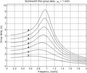
What you see is that the group delay peak comes quite close to the -3dB cutoff of the high pass filter response of the driver and horn combination.Did anyone recall where I said his peak would likely be?
You can look at a Butterworth filter to see the same effect. The peak in group delay comes around the hinge point of the phase shift. The steeper the slope of the filter the more pronounced the peak is and the closer to the cutoff frequency it gets.
Attachments
Beat me to it; observing a rise in group delay at that point isn’t worthy of a ‘eureka’ moment. You’ll see the same on any speaker, and any filter you add for high pass.
Also…
This is a measurement taken in the real-time two-channel mode of Smaart, using the default MTW frequency-dependent window, right?
Unfortunately, I don’t personally class that as a very accurate measurement procedure for the characterisation of absolute phase and by proxy, group delay. It is very easy, but Smaart in real-time mode can make speakers look much better than they really are. That's a side effect of the software's focus on getting 'actionable data' for alignment of multiple speakers at events. 1/6th octave smoothing doesn't help either!
If you use the IR mode, it is easier to post-process as needed, with less chance of introducing error into the data. I use Smaart a lot, but it's also good to know where it's limits lie - and why there are still plenty of awesome measurement platforms that offer non real-time measurements, with a wider variety of data processing as a result.
The later paper by Makarski that I linked a few pages back has an updated method, which negates the need for any microphone measurements, as well as removing the anechoic termination. Instead, an analytical or numerically modelled horn is used as the calibration. In fact, the example is an OS waveguide that's been simulated using BEM. The rest is just the ability to take electrical measurements with high levels of accuracy, and having access to a granite or concrete floor for the rigid termination.
Oh, and some ability to script the horrible maths in something like GNU Octave.
Also…
Here's dcx464/me464 lower section raw on-ax.
"Phase" graph is group delay. Someday the Smaart guys will fix the label when toggling from phase.
View attachment 987137
Good luck with your quest. I ask you count me out for any more measurements towards it though....it seems pointless to me.
i'm simply after how to make better sound than i've ever heard before, which for me means keeping my eye on the 'pragmatic big picture ball'.
This is a measurement taken in the real-time two-channel mode of Smaart, using the default MTW frequency-dependent window, right?
Unfortunately, I don’t personally class that as a very accurate measurement procedure for the characterisation of absolute phase and by proxy, group delay. It is very easy, but Smaart in real-time mode can make speakers look much better than they really are. That's a side effect of the software's focus on getting 'actionable data' for alignment of multiple speakers at events. 1/6th octave smoothing doesn't help either!
If you use the IR mode, it is easier to post-process as needed, with less chance of introducing error into the data. I use Smaart a lot, but it's also good to know where it's limits lie - and why there are still plenty of awesome measurement platforms that offer non real-time measurements, with a wider variety of data processing as a result.
I have used a similar method for just the driver. If you measure the electrical parameters with the driver open and then seal it against some object, you can derive the pertinent parameters of the driver. You do need to estimate the volume of the drivers throat and its length, but a drawing can yield this info. Creating an anechoic termination of a horn would be a most complex task, but its implementation may not be critical.
The later paper by Makarski that I linked a few pages back has an updated method, which negates the need for any microphone measurements, as well as removing the anechoic termination. Instead, an analytical or numerically modelled horn is used as the calibration. In fact, the example is an OS waveguide that's been simulated using BEM. The rest is just the ability to take electrical measurements with high levels of accuracy, and having access to a granite or concrete floor for the rigid termination.
Oh, and some ability to script the horrible maths in something like GNU Octave.
Last edited:
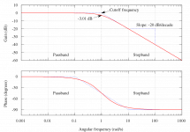
What you see is that the group delay peak comes quite close to the -3dB cutoff of the high pass filter response of the driver and horn combination.
You can look at a Butterworth filter to see the same effect. The peak in group delay comes around the hinge point of the phase shift. The steeper the slope of the filter the more pronounced the peak is and the closer to the cutoff frequency it gets.
Just want to mention that those figure are for a LP filter and would be reversed for a HP. But thanks.
The later paper by Makarski that I linked a few pages back has an updated method, which negates the need for any microphone measurements, as well as removing the anechoic termination. Instead, an analytical or numerically modelled horn is used as the calibration. In fact, the example is an OS waveguide that's been simulated using BEM. The rest is just the ability to take electrical measurements with high levels of accuracy, and having access to a granite or concrete floor for the rigid termination.
That's clever, makes things much easier.
I can show how one can actually measure the drivers nonlinearity via only electrical measurements. Bl(x), Kms(x), etc.
- Home
- Loudspeakers
- Multi-Way
- Is it possible to cover the whole spectrum, high SPL, low distortion with a 2-way?