I dont think anyone noticed that I used krimp connectors plus solder...
Regarding qts...I couldnt get a q of 9 with a box half the size of the 231liter box I'm using...according to hornresp...its gotta be the density 80....or the 16ohm voice coils...I havent asked John yet...or am I using Dats wrong...free air measurement within the box should give me box Q right....the impedance curve looks an undampermed box, fs is 50hz.
Regarding qts...I couldnt get a q of 9 with a box half the size of the 231liter box I'm using...according to hornresp...its gotta be the density 80....or the 16ohm voice coils...I havent asked John yet...or am I using Dats wrong...free air measurement within the box should give me box Q right....the impedance curve looks an undampermed box, fs is 50hz.
Lead wires are soldered to chassis conectors on a transducer on one side. On the other side they are soldered on the voice coil wires.
I don't see a problem with soldering. I use soldering exclusively for 20 years and never had any problem. Crimping with a touch of solder looks like best solution to me.
I don't see a problem with soldering. I use soldering exclusively for 20 years and never had any problem. Crimping with a touch of solder looks like best solution to me.
correct. Np problem to solder when needed, but I would never solder fast-ons (only on the cable tunnel).
Also solder lastly after crimping. If you solder first and then crimp, you might loose the good connection from crimping. The solder will expand when heating up an shrink when cooling down. This happens many times over the years.
Also solder lastly after crimping. If you solder first and then crimp, you might loose the good connection from crimping. The solder will expand when heating up an shrink when cooling down. This happens many times over the years.
Last edited:
Why would you spend all that money on drivers, birch ply etc and then butcher your interconnects. If you want to solder why not solder the bare wire straight to the speakon and slip some heat shrink further up the cable jacket so you can pull it down to cover after soldering.
Agreed, a big time 'cart before the horse' scenario.

Since connections are the weak link in any power signal chain, much better to wire directly to the XO [or driver] and for the record, in my ~20 yrs of being involved in all manner of UL/CSA/MilSpec wiring, bus bar termination testing/certification; cold fusion [crimped] connections with the appropriate hardware proved best whereas soldering was at best just so-so in comparison, though good enough for some apps to justify doing it for budget reasons.
The 'Fly in the soup' though is that the equipment to ensure such connection integrity isn't cost effective for most DIYers or maybe even 'boutique' manufacturers if cost is just inflation adjusted since the early '90s.
If soldering, silver solder with its special flux and clean thoroughly: Beau Tech Component Lead Cleaner | JENSEN Tools + Supply
https://www.amazon.com/Harris-SBSKPOP-Stay-Brite-Silver-Bearing/dp/B0089ETUN2
I don't see a problem with soldering.
There is another side to this story.
I worked in automotive electronics where hand soldering was not allowed under any circumstances. Ford once lost 500 million in warranty and recall costs due to a single (per vehicle) failed solder joint. Only wave soldering was allowed. All other connections had to be done via physical contact with no solder.
In my speakers there was never any solder (from me). Everything was crimped or terminal strips. Sometimes I might miss tightening a terminal, but these were always detectable. Bad solder joints are often not detectable.
Certainly that can be the case, however I'd like to point out that the average home speaker / studio speaker does not endure thermal cycling from -45C to + 65C that an automotive interior does, moreso for the engine compartment.
Did everyone catch that I soldered and crimped the connects? Unless Im doing it wrong, the females weren't easily crimped, so the solder was for extra precautions...the insulated female did not fit all the way down the male...nor did the non insulated male...on that particular tab...due to the size I used in order to accept 10ga...non the less, they are crimped...and soldered....not pretty I take it...I removed the insulation on the one females in order to be able to solder it...its not clicking why fluids connectors would be a good idea...in particular IF they both fit all the way down on the tab...
Last edited:
Did everyone catch that I soldered and crimped the connects? Unless Im doing it wrong, the females weren't easily crimped, so the solder was for extra precautions...the insulated female did not fit all the way down the male...nor did the non insulated male...on that particular tab...due to the size I used in order to accept 10ga...non the less, they are crimped...and soldered....not pretty I take it...I removed the insulation on the one females in order to be able to solder it...its not clicking why fluids connectors would be a good idea...in particular IF they both fit all the way down on the tab...
I meant that
it is now clicking why Fluids connectors would be a good idea
The 10-12 gauge connectors only fit all the way down on one of the tabs. That was issue one. Not being able to crimp the second connector due to how close the damn tabs are was the second issue...so I installed the first connector that would actually fit all the way down...then I used the insulated female on the connector that would only slid about 3/4 of the way down...I'll see if I can redo it and make it look more legit. Probably have to by new connectors since I'm probably not going to be able to get these apart.
I meant that
The 10-12 gauge connectors only fit all the way down on one of the tabs. That was issue one. Not being able to crimp the second connector due to how close the damn tabs are was the second issue...so I installed the first connector that would actually fit all the way down...then I used the insulated female on the connector that would only slid about 3/4 of the way down...I'll see if I can redo it and make it look more legit. Probably have to by new connectors since I'm probably not going to be able to get these apart.
Have a watch of this video it shows clearly why the second type of crimping plier is the one to use.
How to crimp non-insulated terminals | 12 Volt Planet - YouTube
Using the insulated ones and squashing the wire flat is no where near as strong. You can put some solder to reinforce the joint if you end up with wire that doesn't quite fit the crimp but it is very difficult to do it properly. What tends to happen is you end up with a cold solder joint on top of the wire which can still pull out.
The locking connector type are good as long as you never need to remove them. After putting heat shrink over the outside it is quite hard to activate the mechanism to get them off. And you cannot pull them off without it.
This is the Neutrik Faston which is the correct size and the same size as the one I linked to before.
NLFASTON | Neutrik
10 gauge wire is difficult to work with these connectors.
Canare 4S11 works beautifully in both the chassis and plug connectors. The plugs use bare wire with screw terminals and although they can take 10 gauge wire having it a bit smaller makes it much easier. There are also generic equivalents using 2 to 2.5mm cross section cable.
The main reason I try to avoid solder is because it is a pain if you need to take it apart or if you end up swapping parts between projects. Once you have the proper pliers it takes no time to make really good joints. For a one off speaker used at home solder would be fine.
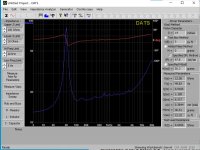

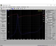
When in the box did you do the Impedance sweep or measure free air parameters? I have never used that particular device but impedance sweep would seem the correct option for in box usage.Am I even interpreting this right? Should qts read as qtc within the box?
- Home
- Loudspeakers
- Multi-Way
- Is it possible to cover the whole spectrum, high SPL, low distortion with a 2-way?