Not from what i've seen. The limitation was presents in the control room i built ( Lafont design from mid 00, absorbent front, diffusing backwall overall very damped with ATC scm110a ) when we played with the monitors location before finalising the built or the Omega A control room ( very big room with TAD TH/TD and et703, 2x TAD 12" each L-C-R with more than 4m between L/R and subs 6x 15"...).
When you talk of 8/10m is it indoor or outdoor? And i suppose this is for live events?
I've found things to be a bit different outside and like you i like this kind of distance but it is so different to the rendering indoor and at this distance i find the experience to be more about the physical feelings of a big soundsystem pushed than correct stereo rendering.
It's indoor, in my apartment.
There are distinct differences between fully treated control/mastering rooms and untreated living rooms.
Tbh, (for now) I don't care too much about the room influences below, say 500Hz, as long as they aren't too annoying.
Above 500 Hz, controlled coverage kicks in and depending on the horn used and the amount of toe-in, I find that distance doesn't really matter, except that the system seems to sound even more coherent at a greater distance.
Last edited:
^ I think it point to the fact we all listen to different things.
When i mix a track i often listen to results in the adjacent place to where i work ( keep the door opened) it gives interesting clues about coherency of the work done.
My room is a little smaller than yours ( 6,6m x 5,7m with -high- vaulted ceiling) and results on backwall are not this bad but nothing to compare with the 'sweetspot' for my preference ( in particular with my Tannoy). But i suspect this have to do with the ceiling and the 90* coverage which 'fills' the room in a nice way imho.
Mark yes 3 times.
But let's take a Dunlavy sc 5 or 6 or Duntech Sovereign. They are 1,9m height so should only be coherent at 5,7m away. But Dunlavy target was 3,3m sweetspot. Another example could be if you managed to keep most ways within 1/4 wavelength at fc ( easier to say than to do).
That is why i'm cautious even if it is not totally untrue.
Last edited:
You could take some very old advice from B&K and measure at least as far away as the longest dimension of the speaker

https://www.bksv.com/media/doc/17-196.pdf
The information Mark posted was to make sure that the speaker was being measured at a point where it was adhering to the inverse square law allowing the measurement to then be scaled to any distance at a relative SPL.
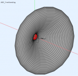
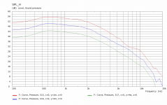
As part of a previous difficult discussion I made a BEM simulation of a horn at 1m, 2m and 4m as you can see by 2m it is pretty much settled and falls at a nice rate of 6dB per doubling of distance thereafter.
What this also shows is that the measurements should be made at the intended listening distance. The difference between 1m and 2m is obvious 2m and 4m not so much.
https://www.bksv.com/media/doc/17-196.pdf
The information Mark posted was to make sure that the speaker was being measured at a point where it was adhering to the inverse square law allowing the measurement to then be scaled to any distance at a relative SPL.
As part of a previous difficult discussion I made a BEM simulation of a horn at 1m, 2m and 4m as you can see by 2m it is pretty much settled and falls at a nice rate of 6dB per doubling of distance thereafter.
What this also shows is that the measurements should be made at the intended listening distance. The difference between 1m and 2m is obvious 2m and 4m not so much.
Attachments
Thinking about this 3x ....as long as ka and ctc didnt get in the way via directivity(for the mtm of course)?
Yes. This is exactly how i see things.
But Fluid is right i think the measurements should be taken at listening point, but most of the time the room is the limiting factor ( in domestic environnement) if you want to stay within direct field ( have you played with the critical distance simulator as it is enlightning).
Well i have nothing agaisnt the 3x distance rule of thumb but as all rule of thumb it need to be taken with a grain of salt ( or at least it require a study of principle applyed to the loudspeaker under test to be sure it is valid or non misleading).
Ro808,
by chance don't you have in your 'bag of trick' Joe D'Apolitto's book on loudspeakers measurements? Thanks for this documents anyway!
Last edited:
+1 if it exists in electronic form I've only seen the paper versionRo808,
by chance don't you have in your 'bag of trick' Joe D'Apolitto's book on loudspeakers measurements? Thanks for this documents anyway!
@ camplo, i was thinking the same thing about an MTM needing 1/2 the 3x rule....given its physical mirror image.
For a giant MTM line the Dunlavy's, there might also be some indoor line array effect going on, which might help close up the distance a little more.
For a coax, i think it comes down to driver/baffle diameter.
.....which is why i'd like to ask ...
@fluid, what was the horn's dia in your BEM sim?
Agreed re 3x being the r-o-thumb for inverse square law taking over.
My understanding is that coherent phase summation of drivers doesn't fully take place until inverse square is satisfied across the frequency spectrum (iow, for all drivers).
Does this jive with your understandings?
Not sure how much that matters though, for folks willing to tune to a near-field spot. As of course anything is possible with such willingness.
@krivium, yep...the 3x rule of thumb definitely comes with a grain of salt, as do all rules of thumb i guess.
My take is 3x makes for a more guaranteed measurement/correction/listening safe zone; whereas inside it comes with increased risk of achieving desired response only for a more narrow spot/zone.
And apart from the phase issue that i mentioned above to fluid, i also like 3x simply to minimize triangulation errors in tuning.
There is always the question where to align the measurement mic on mult-ways.
For example on a two-way CD/horn over cone:
centered on the horn? or centered between the horn and the cone?
I've found getting 3x or more away, helps minimize the impact of that choice...
I know this may sound like picky tuning...but so help me, a dB this way vs that in relative driver levels, and a few fractional milliseconds of time differences between drivers, often makes for something i like the sound of vs something i don't.
I hate that really....i strive for consistent repeatable tuning techniques....that sound consistent and sound great") .
.
I really believe 95% of everything we do in audio fine tuning is hit or miss luck, based on all kinds of vagaries.
(It's why i take subjective A/B opinions with a grain of salt, unless variables are super carefully isolated)
I must emphasize FINE TUNING, not the foundational sound principles we strive to employ.
I'm currently trying to figure out a better outdoor measurement rig to help reduce variances. Because so far, reducing variance is paying off both outdoors and indoors.
Sorry, didn't mean to digress...
For a giant MTM line the Dunlavy's, there might also be some indoor line array effect going on, which might help close up the distance a little more.
For a coax, i think it comes down to driver/baffle diameter.
.....which is why i'd like to ask ...
@fluid, what was the horn's dia in your BEM sim?
Agreed re 3x being the r-o-thumb for inverse square law taking over.
My understanding is that coherent phase summation of drivers doesn't fully take place until inverse square is satisfied across the frequency spectrum (iow, for all drivers).
Does this jive with your understandings?
Not sure how much that matters though, for folks willing to tune to a near-field spot. As of course anything is possible with such willingness.
@krivium, yep...the 3x rule of thumb definitely comes with a grain of salt, as do all rules of thumb i guess.
My take is 3x makes for a more guaranteed measurement/correction/listening safe zone; whereas inside it comes with increased risk of achieving desired response only for a more narrow spot/zone.
And apart from the phase issue that i mentioned above to fluid, i also like 3x simply to minimize triangulation errors in tuning.
There is always the question where to align the measurement mic on mult-ways.
For example on a two-way CD/horn over cone:
centered on the horn? or centered between the horn and the cone?
I've found getting 3x or more away, helps minimize the impact of that choice...
I know this may sound like picky tuning...but so help me, a dB this way vs that in relative driver levels, and a few fractional milliseconds of time differences between drivers, often makes for something i like the sound of vs something i don't.
I hate that really....i strive for consistent repeatable tuning techniques....that sound consistent and sound great
. I really believe 95% of everything we do in audio fine tuning is hit or miss luck, based on all kinds of vagaries.
(It's why i take subjective A/B opinions with a grain of salt, unless variables are super carefully isolated)
I must emphasize FINE TUNING, not the foundational sound principles we strive to employ.
I'm currently trying to figure out a better outdoor measurement rig to help reduce variances. Because so far, reducing variance is paying off both outdoors and indoors.
Sorry, didn't mean to digress...
For a giant MTM line the Dunlavy's, there might also be some indoor line array effect going on, which might help close up the distance a little more.
I guess it is mainly due to the fact that the mid-high section is small compared to other large speakers. And the crossover was also designed for optimal summation at the intended listening distance of 3.3m.
I think that it isn't a bad thing when the optimum listening distance can be pre-set on active crossovers in general.
Regards
Charles
Last edited:
^ Yes i agree with you Charles.
I must confess my choice of the Dunlavy was a bit sneaky ( i know Mark isn't deaf to Dunlavy's approach (as i am too)and i was studying Sovereign and SC-V and VI recently... in relation to Horbach-Keele's approach).
I think that for this kind of layout and from stereophile's interview of Dunlavy he favored omni behavior for the whole loudspeaker and symetric vertical layout ( he insist on this point which make sense for a typical room where ceiling and floor are paralell to have same reflection pattern of ER).
In the second part of Horbach-Keele paper i think fig3 gives another clue about his choice of drivers diam, active bandwidth, cutoff freq and location (which i have not retroguessed, but won't be surprised if the separation ratio of drivers within a couple is 0.333 wavelength at xover freq).
Dave Smith with his approach with what Snell called 'Expanding Array' is interesting too with an approach where he implemented some kind of shading in relation to couple drivers distance/freq of interest too... at the frontier between line array and pointsource approach in my view.
Whatever fig3 helped me to understand Kinoshita RM7 layout choice and MtM in general (as well as Byro tech paper on limitation of MTM).
Last edited:
I would like to add to my testimony of my experience with my current system....I touched on linear phase briefly when the system was 1+8+12 and during that time (which was long ago) I had magical listening session at 1 meter...I have to consider; I'd just reached a new level of expectations...I had a 8" woofer in the system extending the image of bass/midbass source...I haven't played with linear phase since the system changed to a 4" mid. The 4" showed me the benefits of a low Ka...
2=KA for a 15" woofer is 573hz....As long as all the woofers below the tweeter have a low enough KA to support the viewing angle, at 1 meter for example, combined with phase alignment....I think summation will happen at a higher level then general consensus may appear to believe...Moving out in distance from the system may be viewed as a physical time alignment (someone would have to confirm that for me lol) but it sounds feasible considering the correction of spl via viewing angle as well as the viewing angle bring timing closer together or better said, timing offset is exaggerated with close proximity
It might be worth revisiting these systems that are claimed to have better summation with distance and check and see if KA and time/phase alignment wasn't the missing factor (unless you've already done this to confirm results)
2=KA for a 15" woofer is 573hz....As long as all the woofers below the tweeter have a low enough KA to support the viewing angle, at 1 meter for example, combined with phase alignment....I think summation will happen at a higher level then general consensus may appear to believe...Moving out in distance from the system may be viewed as a physical time alignment (someone would have to confirm that for me lol) but it sounds feasible considering the correction of spl via viewing angle as well as the viewing angle bring timing closer together or better said, timing offset is exaggerated with close proximity
It might be worth revisiting these systems that are claimed to have better summation with distance and check and see if KA and time/phase alignment wasn't the missing factor (unless you've already done this to confirm results
)
Last edited:
You guys have left me in the dark concerning horn stands what gives.....I have the 2509a and I think I can increase the hole size with a hole saw....it looks like a hassle to get every centered though...I would think the horn directly attached to the driver would be better and then some other type of stand that supports the unit and is adjustable on pitch...or should I just work with what I have?
+1 if it exists in electronic form I've only seen the paper version
Unfortunately it doesn't, otherwise I would have posted it long ago.
The interview + some posts by J. Dunlavy on rec.audio.high-end (I've deleted all the cable talk).
Attachments
Last edited:
1) Lighten up ;^)1)You guys have left me in the dark concerning horn stands what gives.....
2)I have the 2509a and I think I can increase the hole size with a hole saw....it looks like a hassle to get every centered though...
3)I would think the horn directly attached to the driver would be better and then some other type of stand that supports the unit and is adjustable on pitch...or should I just work with what I have?
2) A hole saw will grab and go off-center. Safer to use a half round file to remove a small diameter difference.
3) Direct attachment would be better, but the thin metal flange of the 2509a shouldn't affect performance much at all if you match the horn/driver smoothly.
Pointing the HF horn at a different angle than the mid driver is a compromise for a specific listening distance.
Focusing (pointing/pitching) the mid-driver/horn to a one meter ear location height will "de-focus" the pair at a further distance.
I said that in jest, I should of added the "lol"....lol
A file? The hole saws have a center drill bit but I guess you already know that?
The design is 41" at the top of the mid cabinet...aiming to give a change of the horn to be at or near 48" which is about ear height for me in the chair that I used for the measurement...which is adjustable and I think I took the measurement with my feet flat on the ground, but I think you'll get what I tried to do...so...if keep the horn pointed straight is the goal, I already have everything headed in that direction, its just this dang stand situation.
- I think you are referring to the stand after the hole has been made to match the exit of compression driver?but the thin metal flange of the 2509a shouldn't affect performance much at all if you match the horn/driver smoothly.
Yes and yes.The hole saws have a center drill bit but I guess you already know that?
- I think you are referring to the stand after the hole has been made to match the exit of compression driver?
IIRC, your problem is the JBL "2 inch" hole is slightly smaller than your horn/driver. Even with a drill press and the stand flange clamped tight to a backing piece secured to the bed, a hole saw is likely to wander and ef up the piece.
A rotary file or sanding drum also works well for removing the portion of a millimeter you want gone, but for that amount of material, a half round file and a strong arm can "get er done" in a few minutes, without having to use heroic clamping and an industrial drill press.
Good luck, be careful !
Art
I don't remember exactly but it would be around 450 to 500mm. You can see from the graph the same things that Pat Brown is talking about, that it is the high frequencies that need the extra distance before they settle down to a steady level. Up until 3 to 4k the level drop with distance is already settled between the 1,2 and 4m simulations.@fluid, what was the horn's dia in your BEM sim?
Agreed re 3x being the r-o-thumb for inverse square law taking over.
My understanding is that coherent phase summation of drivers doesn't fully take place until inverse square is satisfied across the frequency spectrum (iow, for all drivers).
Does this jive with your understandings?
Not sure how much that matters though, for folks willing to tune to a near-field spot. As of course anything is possible with such willingness.
And apart from the phase issue that i mentioned above to fluid, i also like 3x simply to minimize triangulation errors in tuning.
There are also two distinct scenarios for measuring a speaker that might warrant a different approach.
If you are measuring an already designed speaker then getting further away and calculating back makes sense.
If you are measuring to design the speaker crossover then making measurements at the intended listening distance makes sense as you can optimize the summation of the drivers at that distance. Some times there are other considerations depending on where the measurements are carried out as to what will be the best measuring distance. Not everyone has a handy deck to measure off
As to the ka and MTM discussion, it's simple geometry the further apart the drivers are spread the more difference in path length there will be. The closer you are to the speaker the bigger those differences will be and the more likely they will be audible.
Most manufacturers are stuck having to make a choice where they think the majority of purchasers will listen and optimize for that. For diy you can pick the distance you intend to listen at measure or simulate at that distance to get the best result where you will actually listen.
- Home
- Loudspeakers
- Multi-Way
- Is it possible to cover the whole spectrum, high SPL, low distortion with a 2-way?