Not really as you have obviously missed the word "supposedly".")
Bummer
//
To repeat for the umpteenth time, I do not see anything special about the so-called "cutoff frequency." It has no relevance to me.
So no immediate directivity aspect as the horn impedance drops i.e. the loading disappears?
//
Fundamental!
This extract from Don Davis' book is essential to understand the differences between the basic principles underlying the Salmon classical school of thought (Dr. Docali, Jean-Michel Le Cléac'h, RCA, Western-Electric etc.) and modern methods and approaches, such as Dr. Geddes' Waveguide Theory.
This extract from Don Davis' book is essential to understand the differences between the basic principles underlying the Salmon classical school of thought (Dr. Docali, Jean-Michel Le Cléac'h, RCA, Western-Electric etc.) and modern methods and approaches, such as Dr. Geddes' Waveguide Theory.
Attachments
Last edited:
What disturbed me ( i think) is where is the point to use a horn/cd combo outside the range where it does have interesting properties (directivity control for me)?
I see some design where it could help to make 'point source' behavior ( lowering xover point to be within 1/4 wl centre to center distance), or to let the horn alone taking charge of the change in directivity behavior ...but otherwise i don't see the interest in practice ( at least what is of interest to me ).
.
There must be someone else who has noticed as I have that having a compression driver covering 500-1k rather than a woofer greatly improves subjective resolution and the sense of coherence in the midrange. Vocals are much better. I experienced this with 4 different woofers all eqd flat. I can't believe I'm alone in this. As to peak spl capabilities, it is a factor at a certain point I'm sure, perhaps in a very large room. From my perspective, ive seen clip lights flicker on my woofer amps, i believe that's 800 watts, with no strain evident from the compression drivers keeping up.
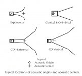
If one measures the impulse response of a loudspeaker at some remote point in space, it is found that a finite time elapses between the application of the loudspeaker excitation and the reception of the response. This time interval is called the transit time. The product of the transit time with the value of the speed of sound that prevails under the conditions of measurement defines a distance.
When this distance is projected from the observing microphone towards the loudspeaker along the loudspeaker axis, the terminus of this projection defines a point in space from which the signal appears to originate. This point is called the acoustic origin. On the other hand, the acoustic center is the point in space from which the spherical wavefronts appear to diverge as observed in the far field. The attached figure illustrates the location of these points for a variety of horns.
It should be observed that only the cylindrical and conical horns have co-incident locations for both the acoustic origin and acoustic center.
Attachments
About loading I think it's not black or white, we can debate a long time but we need to clarify that some theories (or papers) are concerning usual compression drivers only.
Horn loading is important for a compression driver with little excursion capacity, that's logical.
But, for a full range speaker or for the medium-bass drivers of a unity/synergy/MEH loading is not so important, those drivers goes well below the horn theorical "cutoff", they have a different need of loading.
So no immediate directivity aspect as the horn impedance drops i.e. the loading disappears?
//
No not really, the directivity at LF near fc depends almost entirely on the mouth size. There is certainly little or no dependency on the horn shape.
If the "loading disappears" then there is no radiation so there is no directivity.
It should be observed that only the cylindrical and conical horns have co-incident locations for both the acoustic origin and acoustic center.
OS also has this characteristic.
Regarding loading, the real issue is that it is almost always the case that the horns directivity will collapse around fc. That alone is a good reason not to go much below fc.
Last edited:
Constant Directivity (Diffraction) Horns
A constant directivity horn is a hybrid design incorporating aspects from several other horn types. A typical design begins with a throat section having an exponential taper with a cut off frequency well below the lowest operating frequency for which the horn is to be employed. This assures an adequate acoustic load for the horn driver. This throat section furnishes additionally a smooth transition from a circular cross section to a skinny rectangular cross section such that the exit from the throat section is in the form of a slot.
The wave fronts in the interior of the throat section have very little curvature. When these waves encounter the slot two different events occur. A
portion of the wave is reflected back towards the driver as the exit from the throat section represents a discontinuity in the wave medium. The portion of the wave which emerges from the slot undergoes diffraction at the edges of the slot and emerges as a diverging wave such that the wavefront has a small radius of curvature in a plane perpendicular to the length of the slot and a larger radius of curvature in a plane parallel to the length of the slot.
The diverging wave is allowed to expand into a bounded region whose cross-sectional area expands conically except that the horizontal angle is greater than the vertical angle so as to match the differing radii of curvature formed at the slot. Wave propagation in the expanding conical section is well behaved as the horn walls provide a reasonable match for the diverging wavefronts. The wavefronts,of course, are astigmatic by virtue of the differing radii of curvature in the horizontal and vertical planes. With a sufficiently large mouth, the horn coverage angles will be independent of frequency up to a limit where the wavelength becomes comparable to the width of the slot. Beyond this limit the horn will begin to beam. In spite of the constant directivity property, horns of this type have two distinct and serious drawbacks. The internal reflection that occurs at the diffraction slot gives rise to standing wave production with associated resonances occurring in the throat section. The astigmatism associated with the emerging wavefronts from the horn implies separated sources of sound rather than a single point source, as would be the case for a purely spherical wavefront.
Here's my question to Dr. Geddes regarding a "smooth slot", as featured in the 18Sound XR horns shown previously:
As the wave fronts in the interior of the elliptical throat section of these 18Sound horns have curvature and there's no sharp discontinuity - in contrast to the classical diffraction horns, would it still lead to reflection and subsequent astigmatism?
Last edited:
Look at the K402 MEH
A K-402-Based Full-Range Multiple-Entry Horn - Technical/Modifications - The Klipsch Audio Community
This is a quasi OS waveguide (almost? conical then tactrix) which control directivity above 250Hz (look at the polar response plot), 2 ways... It answer to a lot of questions here : 2 ways, loading before "cutoff", good directivity control (approaching shroeder freq ) etc. Perhaps a future project for me.
A K-402-Based Full-Range Multiple-Entry Horn - Technical/Modifications - The Klipsch Audio Community
This is a quasi OS waveguide (almost? conical then tactrix) which control directivity above 250Hz (look at the polar response plot), 2 ways... It answer to a lot of questions here : 2 ways, loading before "cutoff"
, good directivity control (approaching shroeder freq ) etc. Perhaps a future project for me.
Here's my question to Dr. Geddes regarding a "smooth slot", as featured in the 18Sound XR horns shown previously:
As the wave fronts in the interior of the elliptical throat section of these 18Sound horns have curvature and there's no sharp discontinuity - in contrast to the classical diffraction horns, would it still lead to reflection and subsequent astigmatism?
I don't keep up on current products - too many.
As the discontinuity diminishes so will the reflection and the diffraction - so its better, but best is no discontinuity at all.
Yes I know K402 is not OS, it's conical then tactrix it's why I used "quasi"...properties are "almost" the same as OS (my english is limited so it's difficult for me to find the good words...).Your assessment of the K402 is false; it's not a quasi-OS horn (at all)
However, there's currently a pair for sale in Belgium, not exactly cheap though.
Speaking of false assesment you can see that it's possible to go lower than the theorical fc of a horn and that loading is not always important
I leave in Belgium so I like to joke but I prefer building horns myself
Last edited:
Yes I know K402 is not OS, it's conical then tactrix it's why I used "quasi"...properties are "almost" the same as OS
The "mid-section" (after the throat and before the mouth) is similar indeed. Not strictly conical, but close.
This is the cryptic description of Klipsch modified Tractrix contour by Roy Delgado, the designer of the K402:
"The assumption in the wave equation of a plane wave traveling down the horn led many to the assumption of max power transfer occuring in an exponentially expanding area. Change that assumption to spherical, and now max power transfer occurs with a Tractrix expanding area. No, not perfect is right. That is why I say a modified Tractrix equation."
Last edited:
As the discontinuity diminishes so will the reflection and the diffraction - so its better, but best is no discontinuity at all.
Thank you.
Regarding loading, the real issue is that it is almost always the case that the horns directivity will collapse around fc. That alone is a good reason not to go much below fc.
 Works for me.
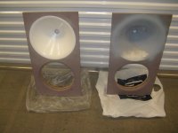
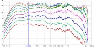
Some additional data of those fullrange 2-ways, shown in #5036:
- 70 degree -6db controlled dispersion modified oblate spheroid waveguide (The "mod" appears to be a LeCleac'h roundover).
- 12 (low mechanical Q) + 1"
- Crossover, presumably between 1500 and 2000Hz.
Quite remarkably, they even published an unsmoothed plot of the waveguide.
"The plots on the right are measurements of just the waveguide, after minimal Eq, we can see we have amazing control off axis in the top range (beyond 20k), each line apart from the first, represents 7.5 degree off axis incriments. So the purple line hovering around 100dB is 37.5 degrees off axis, and just before here we can see at around 35 degree off axis (the -6dB point) it starts to loose control albeit fairly evenly... which is perfect as we wanted a 70 degree guide."
Attachments
Last edited:
- Home
- Loudspeakers
- Multi-Way
- Is it possible to cover the whole spectrum, high SPL, low distortion with a 2-way?