I think what you point out, that the delay of the woofer is already accounted for in a complementary crossover like LinkwitzRiley, is one of the least understood aspects of crossovers.
Thanks, that was in my mind.
...first minimize the physical offset as much as possible physically,
Yes but there are trade-offs and they aren't simple.
I want to keep the horn shallow but I want to have a wide mouth for pattern control and the sidewall angles are fixed to achieve specified cover, damn!
I've found steep linear phase crossovers...help vertical polars
I actually hope to keep the crossover not so steep so I can use the extra width of the horn + woofer to maintain the vertical pattern control a bit lower in frequency.
This is not an idea I have seen discussed much, a bit by Wayne Parham.
It puts further constraints on the system, not sure how much is achievable.
on a two-way like this thread is about, I'd try to get my CD down to wherever I need to cross to the woofer... pattern control and...pistonic frequency response from the woofer.
Yes, I have JBL 2226 for the 15" woofers and they are pistonic to decent frequencies.
670 Hz crossover is my baseline, not least because wave is half a metre, easy to calculate for approximations.
At that crossover freq, I'd use...
Some may balk at this...
The best hardware solution I've found is QSC's Q-SYS. A Core110f would be ideal.
I've seen them go for as low as $750 on ebay.
The QSC is probably twice that price in Australia, in the rare event there is one for sale.
So I'd balk a bit at that, but mainly for the reasons already stated.
Also QSC have some proprietary network IIRC.
Maybe an RME Fireface on USB 3.
Best wishes
David
There are pages and pages discussing various waveguides in the thread, but the DIYSG is never mentioned. I'm wary of the hype posted on other sites and simply wondering if anyone here is familiar with their "SEOS" products.
Every time I look at that website everything of interest is out of stock, specially the waveguides.
Yes, DIYSG isn’t really structured like a business, it’s structured more like a massive group buy that folks can opt in on at their leisure. Unfortunately, their offerings aren’t constantly in supply and a lot of this is due to sourcing issues. I have ordered a lot from them and still have a handful of SEOS waveguides. I’ve built many of their speaker kits and was especially fond of the Fusion 12 loudspeaker (as was my wife).
Bill Waslo (who posts here) was fairly involved with DIYSG before he moved across the country, he also uses the DNA-360 in his printed unity horn.
Hopefully the DNA-360 and the SEOS-15 will both be available again soon.
Before I posted my half silly, half serious response, I went back and re-read your first post, which neither stated nor implied a solo seat app, so not from the get-go. Maybe you read your own posts before taking cheap shots.
GM
I guess I didn't make myself clear
") For that I apologize nor did I intend to insult you! "I've been on a quest to build my own own reference monitor." - I assumed that most peoples take on a reference monitor, in a studio setting, as a one mans show. Ether you are in the triangle or you aren't kinda thing. Especially with intentions of using tractrix/jmlc horn. My fault for assuming.
For that I apologize nor did I intend to insult you! "I've been on a quest to build my own own reference monitor." - I assumed that most peoples take on a reference monitor, in a studio setting, as a one mans show. Ether you are in the triangle or you aren't kinda thing. Especially with intentions of using tractrix/jmlc horn. My fault for assuming.Geddes
Sorry so late, to join the conversation. You commented that angling devices did not work well in your experience? I wonder if I didn't make myself clear? I just meant, to tilt the enclosure/front baffle to point at the ear. Certainly that is no different than turning the speaker to the left or right, in order to once again, point the drivers at the listener.
Please clarify that thought, if you'd be so kind. I do see difference, concerning, the ears performance on different axis and whatever variations of reflective energy.
GM
Sorry I didn't clarify that from the beginning. MTM you say? You like it I love it. ~17" tall per woofer....23" horn.....57" tall MTM...leaving 23" from the top to the ceiling if sitting on the floor.....so floor reflections aren't and issue but ceiling reflections are...is this because of how our hearing works? This would put my horn center at ~29" off the ground....my ears are at 48" off the ground....so now I tilt the whole thing towards my ears right? Or if I move the horn to ear level, The top enclosure is only a few inches from the ceiling....isn't this bad?
I like the idea of the coupling performance of dual woofers when positioned right next to each other....still in the 10.5ft3 enclosure I'm still presenting the idea of tilting the baffle towards my ears
This thread is getting deeeep, you guys are generating great conversation, and I really appreciate you all....as well do other onlookers as well, so much learning and passing of wisdom.
The argument about sealed vs ported, for this projects sake, is null and void. If focusing on a 2 way woofer, there is no sealed woofer that as going to allow sufficient SPL without realizing ridiculous excursion, that would be detrimental to the mid range that it is responsible for. End of story
Also, there are arguments for ported still, is their not? The increased sensitivity....there is a connection between sound quality and efficiency is there not? The trouble with ports exist below the tuning freq or no? (I didn't thoroughly read the whitepaper) with a tuning freq of mid 30's or lower....for music....pretty much everything is going to be above that. Also, aren't there sonic benefits to lowered excursion? I haven't seen too many sealed woofers make to 30hz 0db (linear) without crazy excursion requirements. Maybe I didn't find the right driver. Still, I recognize the advantages of a sealed woofer....its the whole excursion vs mid range performance thing and this is a 2 way project.
Also! Xover...I am copying the xover from the 4722 (630hz)? Seems like a good idea....the polar isn't, unless dead on axis, which is the goal....there was just the concern of the timbre caused by reverberation vs the lobing. Jbl seemed to think it was find for the 4722 =?

ignoring circular waveguide/horns for a second, what merit is there for running traditional PA designed waveguides/horns that are usually setup horizontally, vertically ? especially in a domestic/home environment setup? Would the soundwaves 'blend'/integrate better with the woofer and tweeter(if there is one) as dispersion is wider on the y-axis allowing for a more suitable near/mid-field listening?
this whitepaper, boldly titled: Why Bassreflex is not Suitable for a Subwoofer.
Fundamentally flawed without including VLF EBS alignments.
GM
Ro808
Frankly I don't look much at these pictures because of all the (unknown) variables, and it's usually only an on-axis measurement which tells you very little anyway. And typically I get better results with the same driver put in a proper waveguide. For me these charts are almost useless - either smoothed or much worse than what you can really get.
It depends on the manufacturer.
The curves in the specsheets of P.Audio and 90% of (Asian) B-brands bear little resemblance to reality, as Dr. Geddes stated.
Previously in this thread, it was shown the on-axis response curves can provide usable clues. The breakup of some 3"diaphragm B&C drivers is blatantly obvious in the specsheet. You can also make an assessment of the impact on sound quality. In the response plot 3 major spikes are visible, one of which is very high Q. This suggests multiple badly damped resonances. These will affect performance and cannot be fixed.
In the spectrogram of this driver (posted previously) the breakup (ringing) is clearly visible. Conclusion: the B&C plot is reliable in this respect.
Now if we take a look at the plot of the Faital Pro HF20AT, one medium Q spike is visible, despite the 10dB scale
This suggests the diaphragm is better damped compared to the B&C.
This is confirmed in the spectrogram. While the TAD TD4001 is superior in this respect, the Faital isn't too far behind.
The Faital HF10AK has been referred to repeatedly. Specsheet and measurement data with different horns were posted.
The 'valley' between 1800 and 3500Hz is visible in the specsheet as well as in the individual measurements.
Conclusion: Faital specsheets seem pretty reliable as well.
What's the cause of the dip?
In Faital's archive you'll find a few drivers with the same 21° conical exit section and these al show the same valley.
The dip can be fixed, but it is driver related.
I know a few professionals who are quite obsessed with the curves in the specsheets and pretty much make their buying decisions based on the presented data.
Evidently, the waveguide largely determines the off-axis response.
Sorry of topic: Regarding the HF10AK dip, isn't "the BBC dip" around the same frequencies, a harshness dip? Maybe it is intentional and part of why the driver is mentioned to sound good? Designed for smoother power response transition if used with smaller mid cone and crossed over ~2kHz? Anyone having this dip in their horn speakers eq:d or in the crossover?
Last edited:
I have found my measurement of the HF10 AK on an XT1086 again:
2-Way DiY Hifi speakers eighteensound
I did not have the opportunity to build the box that I inteded to use it in. But I think I would not lift the area of that dip but lower the bump above it and maybe take care of the one below in the crossover. And the rise at the upper end I would leave probably untouched.
Regards
Charles
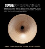
I'm currently at KLIA airport and spotted these. Bass driver is 15-18", the horn is quite a bit bigger. Anyone know what they are?
On closer look these are most likely custom built.
The finish is rather clumsy, as is the design.
The horn looks similar to Zingali's Omniray.
Zingali is quite popular in Asia.
This is a (shameless) clone of the horn:
Attachments
Last edited:
I have found my measurement of the HF10 AK on an XT1086 again:
2-Way DiY Hifi speakers eighteensound
Regards
Charles
Thanks Charles, interesting comments on the 18Sound drivers in the linked thread.
What "special crossover" is this?
Bessel is maximally flat group-delay so looks optimal to me.
It is a "castrated" subtractive delay crossover. I.e. I subtract the lowpass from a second order allpass (instead of a pure delay) with a low Q. The overall group delay will then become that of the allpass function. I.e. the group delay is not flat but it is not very high either and it does show a very gentle down-slope. I know that someone on this forum has also experimented with crossovers of this kind but can't remember who it was. I once used this type of crossover with a prototype using a Beyma coax. Because of the shape and amount of the group delay I could use a phase equaliser of only 10th or 12 th order in front of the crossover in order to achive very flat group delay up to its upper cutoff frequency. With my large MTM the crossover frequency is 650 Hz. This amounts to a crossover-induced group delay of +- 225 microseconds. It would need a phase equaliser of quite a high order to correct that so I just leave it. While this is not perfect - the amount and shape of group-delay achieved this way is below the thresholds shown in a recent AES paper.
Regards
Charles
Last edited:
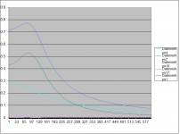
I "abused" my group delay EQ spreadsheet in order to show the difference in group delay behaviour between my crossover and a LR4 crossover both at the same x-over frequency (at data point 138 on the x-axis). The frequency scale is only relative (and linear) but it is still interesting IMHO. The blue trace has no meaning in this comparison. The cyan one is my crossover and the green one is the LR4. The slopes of my crossover are less steep however with 2nd order lowpass and 3rd order highpass. But a 2nd order LR2 for instance would not be an alternative due to the even less steep slopes and the needed signal inversion of one of the filter branches.
Regards
Charles
Edit: Forgot to Mention: The Y axis is also only relative of course. For the Xover frequency of 650 Hz that I use the max GD of my topology is 450us at 0 Hz and for the LR4 it is 690us at 0 hz.
Regards
Charles
Edit: Forgot to Mention: The Y axis is also only relative of course. For the Xover frequency of 650 Hz that I use the max GD of my topology is 450us at 0 Hz and for the LR4 it is 690us at 0 hz.
Attachments
Last edited:
All of that is easy to say in hindsight but you never know in advance. The details are just missing, it can be all over the map and unfortunately the horns used tend not to be particularly good. I don't really look at that much and when there is only a one curve, I don't really give a f***.It depends on the manufacturer. ...
It was not clear at all and you did not say that your statement was specific to a specific case. It sounded like a generalization to me and as a generalization it is incorrect.
The statement "I guess folks see the group delay graph for the crossover going to the woofer, and think it is a substitute for offsetting physical time alignment.
Which of course, it isn't." is clearly false as a generalization. Taken in context, I can see your point.
I'm sorry if it seemed as a generalization aimed toward you...no such intention
I try not to read into what folks say, just take statements as said, and not extend them into generalizations. Communication can be a bitch, eh?
Well I’ve made some progress, whenever the board ignores my inquiries I assume either I’m asking redundant questions or questions that I can answer myself with enough research. So I dig. I emailed the creator of xdir about the spacing setting. The drivers are assumed to have 0 diameter. So it’s edge and center....thus it will show you the polar from multiple areas of a driver pair. You can see from center to center or edge to edge, it’s all valid.....thus, my assumption of the polar was incorrect about how narrow it would be in total...Which is a good thing.
I’ve been back on Winisd looking at excursion, in light of the discussion about sq and sealed woofers....3 td15ms per side? Sealed? Naw that would be too much...hmm
I’ve been back on Winisd looking at excursion, in light of the discussion about sq and sealed woofers....3 td15ms per side? Sealed? Naw that would be too much...hmm
Last edited:
@Camplo, a lot of points in post #2284, not as easy to follow where you're at.
A thought.. An MTM is supposed to take care of vertical dispersion at the crossover. The spacing between the tweeter and one woofer creates nulls which are tilted by the phase difference in the crossover, and are filled in by the other woofer's lobes.
Go down an octave and the woofers are spaced at twice the above distance and you're in the same boat without a crossover. Is it just a matter of which region gets the lobing, (or neither). Is the benefit of MTM the woofers better contribution to lower frequency room modes (not bad).
- Home
- Loudspeakers
- Multi-Way
- Is it possible to cover the whole spectrum, high SPL, low distortion with a 2-way?