Project May on the Lansing forum might be of interest.
Attachments
Last edited:
The woofers on the Ocean Way definitley look like TAD. I'm having troubles believing the frequency response in that data sheet, the low-end extension in particular.
Regards
Charles
AFAIK the woofers are indeed TAD units.
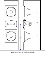
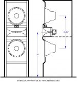
I have never used two woofers so I don;t have a lot of experience. Multiple sources over the same frequency range will always create problems that we don't want so its best not to do that unless it is absolutely necessary, and I have not found this to be the case.Gedlee, I just meant that, one of the drivers will be farthest away from being on axis....deciding which & how to locate the drivers. With TMM, the bottom woofer would likely be that driver. I can angle the horns. I am pondering how dramatic of an angle would still be acceptable given the 630hz xover and 15" woofer size....this is pertinent because of the desired near field listening position. Though not optimal, I must make the best of it.... Using a stand or floor standing, to put the 15"s closer to ear level raises the height of the horn.... I don't know how I'd like the tops to be coming from "above" so if I put the top of the top woofer at ~47" (basically ear level) that puts the center of the Horn 11.5 inches above and the center of the 15", ~8" below....and the center of the bottom 15" ~24" below that....I'll have to go back and read on our last discussion that lead me to feel comfortable with TMM.......If I did the upside down V shaped MTM with the woofers placed horizontal, from my reading, comb filtering will occur.....Read that as "will occur?" Looking for some confirmation I guess...I think someone already suggested that what I believe to be true on the matter, so......so, TMM it is I guess. I've seen upside down V shaped MTM with side by side woofers....Did no one tell them about the comb filtering?
At 10.5 ft3, floor standing is the only practical option to try and eat up some of the volume
H47" W25" D22"
Panel thickness 1"
Actually this is a perfect opportunity to clear up the idea of the formula for KA....I've basically adopted the formula from your paper on directivity, Gedlee, while others have accepted the approach of dividing speed of sound by diameter to discern a KA=2....what do you think of this?
Vertical spacing would be preferred however as it is the horizontal directivity that is so critical, not the vertical.
KA is impy defined as twoPI*frequency * radius / c - anything else is not correct.
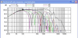
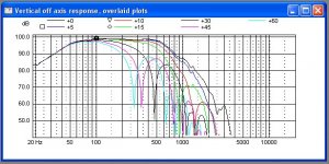
"Don't confuse comb filtering with lobed response. Comb filtering occurs on the horizontal plane only when drivers are horizontally placed. Don't do that and there's no problem. Lobed response can be a problem with vertically aligned drivers at too close a listening position, but at usual distances wavefront integration is complete. Even Joe D'Appolito doesn't worry about keeping CTC to a wavelength anymore, and he should know.
I do question the MMTMM idea. The T might not keep up with all those Ms."
-billfitzmaurice
Both comb filtering and directivity stem from phase differences in sound path, so they are similar phenomena, but yet the two terms imply different things. Comb filtering usually applies to room reflections and not free field issues. Directivity is a free-field issue that does not depend on room reflections, although one can certainly argue thet they result in the same thing in the same situations.
I am not sure, but I think Marcel somehow anticipated the disappearence of the aberrations with a sufficiently large mouth size and roundover.
The sims were posted in his local forum, so I have to rely on google translate for the interpretations of the comments.
This is the translated comment he posted along with the sims of the 52cm OSWG:
"Even with pure OSWG, excellent results can be achieved. As it is obvious from all this, the key is a sufficiently smooth outlet. Specifically, this is already 52 cm in diameter. Then even the circular symmetry will not have any negative effect (at least not visibly from these graphs).
Ie. if you do any horn, the bigger will always be better, and certainly not spare on a smooth outlet."
Outlet translates into "mouth roundover" I would think.
And later:
"The 52 cm was just a random number, of course related to how low it keeps the beam."
This is what he did (in ABEC) concering the 18cm OSWG, in order of appearance from left to right:
- flat 'cap'
- spherical cap
- SPL with spherical cap
- polar map with spherical cap.
The underlined statement is clearly true.
The use of a cap or a dome in theory should result in the exact same results. However, it can be difficult to know what the wavefront looks like on either surface and so one has to make some assumptions. These assumptions will generate differences if either one is not correct. For example, the flat case would have a great deal of phase and amplitude variation across it since the wavefront is not flat in that surface. The spherical dome would be more correct for a uniform velocity, but still assumptions about this wavefront may be in question, leading to erroneous results.
One related question to the experts: how is the function of the diffraction slot influenced by making the horn longer with the adapter?
Most of the problem with diffractions slots are due to the large reflection that occurs from this interface. These reflections move back down the device to the diaphragm causing large peaks and dips in the response. For the most part the outer portion of the device has little effect on these problems. A longer "adapter" between the diaphragm and the diffraction slot will lower the frequencies of the resonance peaks creating more of them in the passband. Its best not to have any internal reflections in a waveguide or horn. Nothing can be done with diffraction that cannot be done without it, although a diffractionless waveguide will tend to be bigger that a diffraction horn for the same coverage.
Your eyes, ears are horizontally opposed, so vertically oriented sights, sounds have a narrow focus, hence not a lot of spacial information to work with; horizontally though, 'smearing' due to lobing, comb filtering is an increasing problem above the ~800 Hz head transfer function [HTRF].
Anyway, this is [one of] Dr. Geddes's fields of endeavor, so looking forward to any thoughts/corrections/whatever.
GM
This is, of course, a big issue with me. Horizontal aberrations lie in the same plane as our ears and as such are far more serious than vertical ones, almost to the point that we can ignore the vertical as long as we take great care with the horizontal. There are some issues with floor and ceiling bounce in small rooms, but I take care of those in the room, not in the speaker design.
This is a very good question.
AFAIK the inner workings of diffraction slots are very hard to desribe mathematically. IOW it's difficult to 'predict' the wavefront inside and after the slot at one particular frequency, let alone across the band.
Read Kolbreks thesis on 'mode matching' to find out. He couldn't really get passed the 'pinched throat' case, which is just one feature of some slotted horns. Modern diffraction slots are developed by use of computational techniques (FEA etc.).
I am looking forward to Dr. Geddes' reply, even though I am perfectly aware he 'doesn't like diffraction slots', to put it mildly.
Diffraction slots have their merits and they can work very well, if implemented with care. Earlier in this thread some examples were cited.
No, I do not like them. All of my early speaks had them and they all had the same harsh sound. It was not until I made a waveguide and heard how clean a diffractionless device is that I fully understood the problems with diffraction slots.
Modern simulations can mitigate the problems with diffraction, but never eliminate them as long as there is an abrupt change in the wall contour. Diffraction is highly audible and all efforts to eliminate it will pay big dividends.
These days loading isn't something that many manufacturers worry about, as most compression drivers are used with short horns.
Loading, to me, is all but irrelevant. The length of the horn doesn't really affect loading nearly as much as the flare rate.
IMHO high directivity horns are low-fi devices ...
I think that this is completely the opposite. High directivity minimizes the very early reflections (VER) that are so detrimental to imaging. WIde directivity - many VER, narrow directivity - fewer VER.
I design for the highest directivity that I can get in a reasonable size. The higher and flatter the DI(f) the better. The NS-15 and the NA-12 have almost identical frequency response and DI(f), but the NS-15 DI(f) is a few dB higher and this makes it sound just a little better.
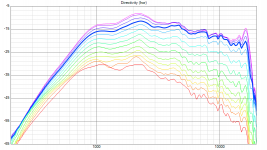
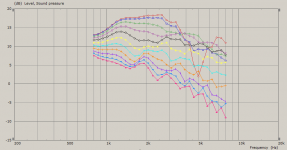
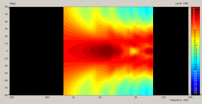
I somehow missed this whole conversation. It's the size and the smooth roundover. I use Euler spiral (clothoid) for the termination, typically from about a half of the depth of the horn outward - it turned out as a really convenient shape for this. Now I have so plenty of such results that I almost could make a proper study for the "axial issues" (as I'm quite busy these days I hoped someone else might do it since I released the tool but that seems not going to happen).Yes, the axial issues are better represented in those pics. What's the difference?
Originally I started to develop on non-axisymmetric designs but when I fiddled with different roundovers and horn sizes I quickly realised that I can still make quite perfect axi-symmetric waveguides. So now I'm kind of returning back to those as I still see some points in the axial symmetry in general and I believe it is a good thing, especially when got rid of these axial issues. It can be done!
It can be done!
Of course "it can be done", I've been doing this and known these relationships for decades.
In your models how do you specify the source velocities? These aren't really known exactly are they?
Some interesting info I found. 650hz crossover. 2nd order. Check the manuals of the various models
OceanWay's smaller monitor also has 2 pole filter. Impressing sounding speaker.
Pro2A – OceanWay Audio
Consumer version is this.
Ocean Way Audio Speakers
$7000, but you can build a pair with SB+Seas for much less than 10% of that.
") It can be a great DIY project!
It can be a great DIY project!
Last edited:
Now it's constant. Either the velocity or the acceleration (mostly). I don't do anything more.In your models how do you specify the source velocities? These aren't really known exactly are they?
Earl, for me it was a surprise (or a discovery in fact) - now I know you know it. It's hard to really appreciate without own experiments. That being said, I still haven't seen any of your waveguides performing as good as this (quite a small) one - to tease you a bit
Attachments
Now it's constant. Either the velocity or the acceleration (mostly). I don't do anything more.
Earl, for me it was a surprise (or a discovery in fact) - now I know you know it. It's hard to really appreciate without own experiments. That being said, I still haven't seen any of your waveguides performing as good as this (quite a small) one - to tease you a bit
To me that looks quite like my largest waveguide. I would certainly not say that it is any better, or worse.
Uniform velocity is a simplifying assumption that is not entirely correct. I have measured standing waves across a waveguide mouth resulting from the edge diffraction. This will not have a uniform velocity contour.
Last edited:
I somehow missed this whole conversation. It's the size and the smooth roundover. I use Euler spiral (clothoid) for the termination, typically from about a half of the depth of the horn outward - it turned out as a really convenient shape for this. Now I have so plenty of such results that I almost could make a proper study for the "axial issues" (as I'm quite busy these days I hoped someone else might do it since I released the tool but that seems not going to happen).
Originally I started to develop on non-axisymmetric designs but when I fiddled with different roundovers and horn sizes I quickly realised that I can still make quite perfect axi-symmetric waveguides. So now I'm kind of returning back to those as I still see some points in the axial symmetry in general and I believe it is a good thing, especially when got rid of these axial issues. It can be done!
Marcel, thanks for joining in!
It felt a bit awkward posting your sim results and comments.
To me it was the first step, just to see the basic trends. Any ideas how to make the sims more realistic would be highly appreciated. I'm really not an expert in this - I can't even pretend. I just use what is readily available (ABEC) the best way I can...Uniform velocity is a simplifying assumption that is not entirely correct.
Oh, maybe I misunderstood. As a source velocity I meant the wavefront at the throat. From that on the BEM simulation takes over. I make no other assumptions about the velocities anywhere else.Uniform velocity is a simplifying assumption that is not entirely correct. I have measured standing waves across a waveguide mouth resulting from the edge diffraction. This will not have a uniform velocity contour.
What you saw earlier (a cylinder or a cap) "in front" of the WG is just a way how ABEC organizes the calculations. It called "interface" and its actual shape shouldn't really matter much.
Last edited:
To me that looks quite like my largest waveguide. I would certainly not say that it is any better, or worse.
Uniform velocity is a simplifying assumption that is not entirely correct. I have measured standing waves across a waveguide mouth resulting from the edge diffraction. This will not have a uniform velocity contour.
Would this still matter in case of an oversized waveguide, say: 1 meter in diameter for a crossover at about 800Hz?
Last edited:
For anyone's interest, this is how it looks like for a straight cone in a infinite baffle (as all the sims I made so far are for IB) -
Ro808: I make no assumptions about the velocity at the mouth - that is really calculated and I would guess it will be quite right. I only assume a flat wavefront at the throat.
Ro808: I make no assumptions about the velocity at the mouth - that is really calculated and I would guess it will be quite right. I only assume a flat wavefront at the throat.
Attachments
Last edited:
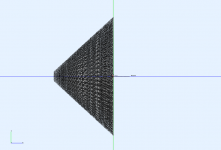
I'm glad you say that because this horn is only 374 x 351 x 130 mm.To me that looks quite like my largest waveguide. I would certainly not say that it is any better, or worse.
Attached is the STL file. It's basically an OSWG with a bit of induced non-axisymmetry.
Attachments
For anyone's interest, this is how it looks like for a straight cone in a infinite baffle (as all the sims I made so far are for IB)
Where is the back wavefront ?
It should looks like that
...i'm far away
- Home
- Loudspeakers
- Multi-Way
- Is it possible to cover the whole spectrum, high SPL, low distortion with a 2-way?