Measurements from Hobby HiFi 6/2017
Hi
In the measurements from Hobby HiFi 6/2017, there is a peak of 5 dB on axis compared to 15 degrees of axis at 5 kHz.
Toni G As far as I can see in the picture, you cover both sides of the V with wood. That is not what I propose.
I propose a thin strip ( 3, 4, 5 ..... 10 mm) of som absorbant material (felt, acoustilux or anything) right on axis. Maybe trying different shapes of the strip too. Like round, flat, triangular or romboid.
best regards
Uwe
The crossover circuit that you have drawn with the red circled components is not correct. You have shown a series resistor and inductor combination that is in parallel with the treble speaker. What I do is fit a parallel resistor and inductor in series with the treble speaker. Incidentally the inductor value is 0.065 milli Henries. This network should be fitted between the 'L' pad and the tweeter and preceded by the 2nd order crossover network. The corrected ESS HEIL AMT has an average sensitivity of 95 dB from 3 kHz upwards for a 2.83 volt signal at 1 m on axis. Your crossover and 'L' pad may require some adjustments of component values to take into account the impedance of the AMT in the crossover frequency region.
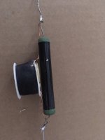
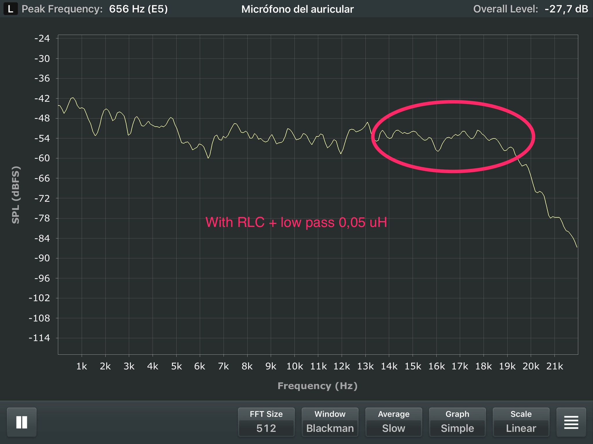
finally, with a LCR meter, I have transfromed a coil that I already had at a value of 0.065 mH. together with a resistance of 22 uf I can make your proposal. Is the placement correct that can be seen in the photo?
Attachments
Did you see this thread, specifically posts #33 and #34 where they discuss how to fix the 5 KHz and 12 KHz problems?
To Heil AMT or not to Heil at $140, that is the question?
thanks for the info. I already knew the article cited and, in fact, I have cited it in this thread.
BR
From the photo , it appears to show the correction network fitted before the L pad. This needs to checked and corrected if it is the case ; the circuit drawing shows the correct position. The violet lead is the positive lead connecting to the AMT.finally, with a LCR meter, I have transfromed a coil that I already had at a value of 0.065 mH. together with a resistance of 22 uf I can make your proposal. Is the placement correct that can be seen in the photo?
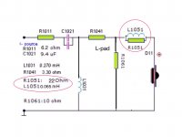
In a previous post I suggested changing the values of R1041 to 2.75 ohm and R1061 to 9.1 ohm ( and deleting R1011). These new values would result in the combination network presenting a 6 ohm impedance in the crossover region. The values for C1021 and L 1031 for a B2 network, should then be 8.1 mFd and 0.587 mH respectively for a 2300 Hz crossover frequency. The alternative LR 2 crossover network would require; 5.7 mFd and 0.83 mH components.
TONI,
Here's a 2300hz HiPass for you to play with ( level will need to be adjusted to match your existing speaker > whatever that is ).
- 2300hz is @ 6db down from 4K.

The .dxo file is included for those who wish to play.
- FRD + ZMA files were created using RobH's pics ( with a further 5db of attenuation added bringing the overall raw sensitivity to right around 100db ).
")
Here's a 2300hz HiPass for you to play with ( level will need to be adjusted to match your existing speaker > whatever that is ).
- 2300hz is @ 6db down from 4K.
The .dxo file is included for those who wish to play.
- FRD + ZMA files were created using RobH's pics ( with a further 5db of attenuation added bringing the overall raw sensitivity to right around 100db ).
Attachments
Thanks for the info. In order to confirm that I have correctly understood the information that you provide me, these are the values that I have understood.Hello TONI
Here I blew it up to make it easier read. It is a .075u with a series .33 resistor to lower the Q and broaden the notch. To make the .075u I purchased a .100u and took some windings off measuring on a WT2. The DCR of the coil is about 60 mili ohms to get closer to the target of .4 ohms total. I also attached a measured vs. predicted so you can see the on axis response is with the notch and the active 24Db L/R crossover. The others resistors were bring up the DCR overall to about 8 ohms. I loose about a 1db to or so overall.
Even though there is still a rising response it sounds good to me as the overall power response tends too flattens this out.
Rob
R11: 0.33 omh
L3: 0.075 mH
C7: 12 uF
R9: 8 omH
BR
Toni
From the photo , it appears to show the correction network fitted before the L pad. This needs to checked and corrected if it is the case ; the circuit drawing shows the correct position. The violet lead is the positive lead connecting to the AMT.
In a previous post I suggested changing the values of R1041 to 2.75 ohm and R1061 to 9.1 ohm ( and deleting R1011). These new values would result in the combination network presenting a 6 ohm impedance in the crossover region. The values for C1021 and L 1031 for a B2 network, should then be 8.1 mFd and 0.587 mH respectively for a 2300 Hz crossover frequency. The alternative LR 2 crossover network would require; 5.7 mFd and 0.83 mH components.
Thank you very much for your help, I appreciate all your advice. The coil and resistance of the photo is placed in the same place as the diagram. The problem of the changes that you suggest that forces me to change the cap and coil that I have currently installed. The cap in particular is a Duelund and its price is very high. I am very happy with its sound and my intention is to maintain its use since I do not have the economic possibility to choose other values while maintaining the quality of the current components. Another issue is to replace or add other circuit components such as resistors or RLC circuits. I have evaluated the effect of the incorporation of the circuit of the coil and the resistance of the photo and my impression is that it incorporates a "high pass filter" that softens the entire area of the treble end (including the problematic frequencies). It seems a good solution. I hope to be able to make some measurement "with" and "without" this circuit.
BR
Toni
TONI,
Here's a 2300hz HiPass for you to play with ( level will need to be adjusted to match your existing speaker > whatever that is ).
- 2300hz is @ 6db down from 4K.

The .dxo file is included for those who wish to play.
- FRD + ZMA files were created using RobH's pics ( with a further 5db of attenuation added bringing the overall raw sensitivity to right around 100db ).
Thank you very much for the help. The circuit that you attach to me seems very interesting since it respects the values of the two main components of my current filter and, from what I understand, selectively corrects the area with the main peak of the ESS and tends to flatten the entire response of the ESS .
A concern that I have with the solutions that are incorporated in "series" to the crossover is that, I understand, requires that the quality of the components be good. Particularly in the circuit that you propose, the 0.04 mH coil seems to have an important influence on the final result. You think that one type of coil may be more appropriate than another (for example, ribbon coils, etc.).
BR
Toni
<<<<<SNIP>>>>
A concern that I have with the solutions that are incorporated in "series" to the crossover is that, I understand, requires that the quality of the components be good. Particularly in the circuit that you propose, the 0.04 mH coil seems to have an important influence on the final result. You think that one type of coil may be more appropriate than another (for example, ribbon coils, etc.).
BR
Toni
You can easily leave out the 0.04 mH coil ( I would ).
It's effect is exceedingly mild ( averaging 1db ).
See;
That coil was included simply to "make-it-as-flat-as-possible" ( as an exercise ).
I know that I would leave it out for my own hearing ( UHF compensation )
Attachments
Last edited:
TONI,
Here's a 2300hz HiPass for you to play with ( level will need to be adjusted to match your existing speaker > whatever that is ).
- 2300hz is @ 6db down from 4K.
The .dxo file is included for those who wish to play.
- FRD + ZMA files were created using RobH's pics ( with a further 5db of attenuation added bringing the overall raw sensitivity to right around 100db ).
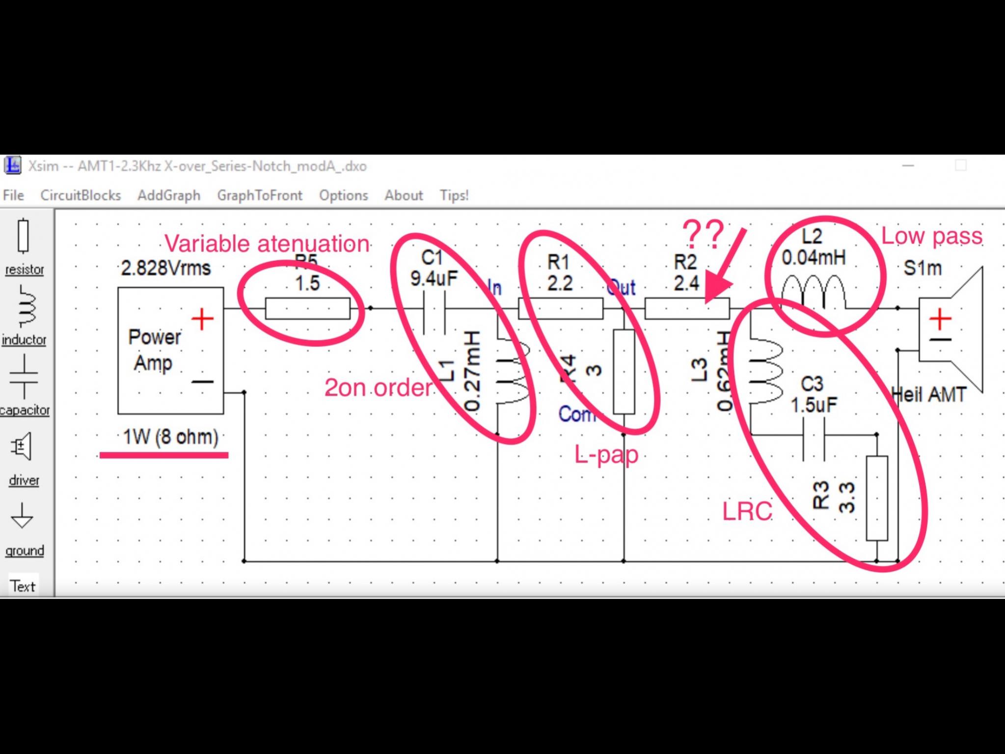
Hi, I would like to understand the design of the crossover. I attached a photo with the operation that I understand. What is the function of the indicated resistance? What does the "8 omh" of the underlined text mean?
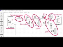
Sorry, here is the photo
R2 is simply part of an adhoc "T-Pad" .
I used a "T" pad ( instead of an "Lpad" ) since it offers better isolation for the LCR ( NOTCH ) parts following it.
R2 is simply part of an adhoc "T-Pad" .
I used a "T" pad ( instead of an "Lpad" ) since it offers better isolation for the LCR ( NOTCH ) parts following it.
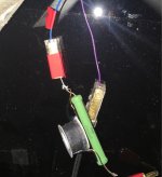
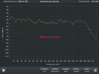
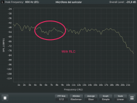
Hello, finally I have applied the rlc circuit in the current crossover (without modifying the l-pad circuit) and a coil of 0.05 uh. I have made some measurements from the point of escuha with the two channels. I attach the measurements. Beyond the measures, the effect is perfectly audible.

Hi Toni,
If you desire more overall level from the Heil then make the R5 resistor smaller.
One only needs to parallel any value resistor to the existing R5 ( 1.5R ) to arrive at a smaller net value.
You might start by adding another 1.5R to R5 ( giving a 0.75R value ) to see if the increase in HF level is attractive.
Apart from the above, how does this custom setup currently sound to you ?
Ess Heil 3rd order crossover 2.8Khz
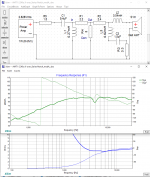
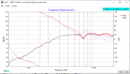
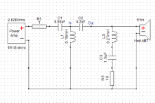
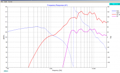
Another option for those looking for crossover guidance. I eliminated most of the resistors because I may use this with some pro high-efficiency mids, and I changed to 3rd order to protect the tweeter from high power. Note the 3dB divisions in the graph - about +- 2dB from 2.8Khz - 16KHz. I have not measured this version yet.
Another option for those looking for crossover guidance. I eliminated most of the resistors because I may use this with some pro high-efficiency mids, and I changed to 3rd order to protect the tweeter from high power. Note the 3dB divisions in the graph - about +- 2dB from 2.8Khz - 16KHz. I have not measured this version yet.
Attachments
genius
Well, first of all, you are a 'effing crossover genius. No doubt.
Xsim is showing about 1 dB lift 12-18Khz when I use a 8.2 uF cap across the 1 ohm resistor. Every little bit helps, but this is just a sim at the moment. Wanted to provide a bit of support for some of these guys. The real work starts after I build a box for the mids and woofer.
I'm really very pleased a how the sim has been able to flatten out the raw FR.
You could pop a 1.0uF across the 1 ohm resistor and lift the top-end a smidge.
Later,
Wolf
Well, first of all, you are a 'effing crossover genius. No doubt.
Xsim is showing about 1 dB lift 12-18Khz when I use a 8.2 uF cap across the 1 ohm resistor. Every little bit helps, but this is just a sim at the moment. Wanted to provide a bit of support for some of these guys. The real work starts after I build a box for the mids and woofer.
I'm really very pleased a how the sim has been able to flatten out the raw FR.
- Home
- Loudspeakers
- Multi-Way
- ESS AMT tweeter. Help for correct use