If your using a balanced amp with inverted and non-inverted signals on either end for passive multi-way speakers wouldnt it need a special crossover to filter the inverted signal too?
Balanced speaker amps dont seem to be very common,
though there are relatively easy ways to DIY.
Balanced speaker amps dont seem to be very common,
though there are relatively easy ways to DIY.
If your using a balanced amp with inverted and non-inverted signals on either end for passive multi-way speakers wouldnt it need a special crossover to filter the inverted signal too?
Nope.
I advise you to read and understand what is the purpose of balanced interconnection:
Sound System Interconnection
Balanced (fully symmetrically built) equipment is rare and it is not necessary at all unless it is your intention to waste money on component doubling. Engineer should put symmetrical circuits only where they are necessary - line receivers and drivers prone to noise contribution. Interconnecting cable is also a part of the system prone to noise contribution if the signal level is low.
Last edited:
Nope.
I advise you to read and understand what is the purpose of balanced interconnection:
Sound System Interconnection
Balanced (fully symmetrically built) equipment is rare and it is not necessary at all unless it is your intention to waste money on component doubling. Engineer should put symmetrical circuits only where they are necessary - line receivers and drivers prone to noise contribution. Interconnecting cable is also a part of the system prone to noise contribution if the signal level is low.
I thought it was clear I meant balanced amp, not interconnection.
Class D chip amps are cheap, common and very easily configured like this, essentially doubling output power and far from a waste.
but that isnt relevant, the question was regarding crossovers after the balanced output of an amp.
Last edited:
Gauder Akustik builds a symmetrical parallel crossover'ed speaker. They don't demand it, but best results are obtained with balanced amplification.
laserscrape, using the word 'balanced' confuses people. It should only be used for amplifiers, pre-amplifiers etc. For speaker crossovers, symmetrical is the word.
Atma-Sphere, BAT (Balanced Audio Technology), Macintosh Quad Differential, Giordini, Consummate, Gryphon, Krell (older models). The list goes on. All these amplifier manufacturers have a unifying belief; the entire sinusoidal waveform must be preserved. The +ve terminal pushes the driver out, the -ve terminal pushes the driver in. Notice how i didn't say push and pull?.
Let's take their mono-blocks. If you open one mono-block up, you will see two identical amplifiers inside. If the wires aren't colored, you would never know which is +ve or -ve. The entire waveform is preserved.
Who cares. Since every crossover (except Gauder) is asymmetrical, the balanced nature of the waveform is distorted. Hence, most people don't spend the money on balanced amplification. I did.
Where did the RCA interconnect come from? The audio industry wanted to bring HiFi to the masses. The center barrel is the positive portion of the waveform. Good start. The outer ring is the negative portion of the waveform, but it is referenced to ground. By adding a small inexpensive circuit, they restore the waveform. Problem; even at the speed of light, there is a lag. Who cares, you get really good sound, at a much lower cost. Human nature has shaped the audio landscape, not perfect sound reproduction.
You're starting down a slippery slope. No one here will support your thoughts or theories. PM me.
You're starting down a slippery slope. No one here will support your thoughts or theories. PM me.
It seems somebody's already on a slippery slope.
My goodness.
Dave.
You mean put identical series components into each of the [nominal] positive & negative legs of a passive crossover? Well, you can do if you like, there's nothing to stop you. You'll need four times the total series capacitance (x2 in each leg) and divide up the relevant series inductance and resistance between the legs. Since it costs significantly more, requires more space as you've doubled the amount of components and provides exactly the same transfer functions, most people don't bother as there isn't much reason to do so.
In fairness, I know somebody who did it, and using extremely expensive components too. He was happy; whether he would have been equally happy with a simpler & cheaper conventional approach is open to question.
In fairness, I know somebody who did it, and using extremely expensive components too. He was happy; whether he would have been equally happy with a simpler & cheaper conventional approach is open to question.
Last edited:
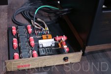
Rey Audio does it.
Rey Audio does just that, albeit only for the Woofer section of the crossover (which is a 6th order low-pass).
Here's a photo of one of their crossovers (attached).
You can see the six series inductors (three on the "+" leg, and three on the "-" leg) on the left-hand side of the crossover board.
You mean put identical series components into each of the [nominal] positive & negative legs of a passive crossover? Well, you can do if you like, there's nothing to stop you. You'll need four times the total series capacitance (x2 in each leg) and divide up the relevant series inductance and resistance between the legs. Since it costs significantly more, requires more space as you've doubled the amount of components and provides exactly the same transfer functions, most people don't bother as there isn't much reason to do so.
In fairness, I know somebody who did it, and using extremely expensive components too. He was happy; whether he would have been equally happy with a simpler & cheaper conventional approach is open to question.
Rey Audio does just that, albeit only for the Woofer section of the crossover (which is a 6th order low-pass).
Here's a photo of one of their crossovers (attached).
You can see the six series inductors (three on the "+" leg, and three on the "-" leg) on the left-hand side of the crossover board.
Attachments
Hi Marco
Do you know the reasoning behind that ? And are those the original inductors shown on that crossover or special ones replaced by Kenji ? Or are they supplied by some Italian salumeria ?")
For the OP: Of course you can do a symmetrical crossover but the amp does not care at frequencies from DC up to the ultrasonic range. The slightly asymmetric load condition would only be measurable at RF frequencies.
Regards
Charles
Do you know the reasoning behind that ? And are those the original inductors shown on that crossover or special ones replaced by Kenji ? Or are they supplied by some Italian salumeria ?
For the OP: Of course you can do a symmetrical crossover but the amp does not care at frequencies from DC up to the ultrasonic range. The slightly asymmetric load condition would only be measurable at RF frequencies.
Regards
Charles
Hi Marco
Do you know the reasoning behind that ?
In an interview that he gave to the magazine Studio Sound in July 1987, Mr. Kinoshita claimed that it reduces "cross talk" between the Woofer and Mid-tweeter branches.
And are those the original inductors shown on that crossover or special ones replaced by Kenji ? Or are they supplied by some Italian salumeria ?
Those are the original inductors.
For the OP: Of course you can do a symmetrical crossover but the amp does not care at frequencies from DC up to the ultrasonic range. The slightly asymmetric load condition would only be measurable at RF frequencies.
Regards
Charles
Marco
Hi Marco
Yes, there can be indeed some reduction in crosstalk but it is diffucult to say by how much compared to a properly layed out ordinary asymmetric wiring (especially if the ground wiring of the latter is properly done).
Interesting interview. I even know the interviewer by accident.
Regards
Charles
Yes, there can be indeed some reduction in crosstalk but it is diffucult to say by how much compared to a properly layed out ordinary asymmetric wiring (especially if the ground wiring of the latter is properly done).
Interesting interview. I even know the interviewer by accident.
Regards
Charles
Dear all,
as I have a balanced amplifier, I was worried about the same as the TO. Scottmoose is of course right, the symmetrical or balanced filter is, given you realize it in good quality, a lot more expensive than a "normal" filter.
In short, I simply tried it, first for my wideband driver filter. Together with my balanced amp, I found the symmetrical approach to be a little bit clearer and more 3-dimensional.
Bass filter has yet to come, no time in the moment...
All the best
Mattes
If there is something audible in to it, better think in terms of electrical damping and parts distortion in regard to the doubling of passive crossover components which also have DCR & ESR, than in terms of balanced large signal. Because the two terminal speaker transducers are hanging there inherently current balanced anyway.
The bridged amplifiers source, also called balanced, ups some damping ratio per phase side with the increased and evenly distributed parasitic impedance downstream. Unless you select the parts and layout wires for same total parasitics as in conventional version. The doubled up passive filter parts now work at half the signal voltage across them for the same output level. Capacitors especially, increase their THD with higher signal voltage level.
The bridged amplifiers source, also called balanced, ups some damping ratio per phase side with the increased and evenly distributed parasitic impedance downstream. Unless you select the parts and layout wires for same total parasitics as in conventional version. The doubled up passive filter parts now work at half the signal voltage across them for the same output level. Capacitors especially, increase their THD with higher signal voltage level.
- Status
- This old topic is closed. If you want to reopen this topic, contact a moderator using the "Report Post" button.
- Home
- Loudspeakers
- Multi-Way
- balanced crossover?