(
Indeed. The midwoofer is perfectly flat 1st order acoustic, the bass driver is really close to true1st order acoustic based on early calculations. The tweeter starts at 1st order and ends with 2nd or more due to series LCR. The midrange is the only one that's choppy and nowhere near 1st order acoustic, Im gonna start looking for an alternative, but I need 90db sensitivity, and my prior weapon of choice mca15rly is only 87.5db, and mr13p has rising response which doesnt work with 1st order. I'll be back with some more midrange picks, because that Chinese one in the first post was also choppy. I need a midrange flat to 9000hz, with 90db sensitivity and 8 ohms. Candidates?
OK just checked, nothing better. Illuminators, Revelators, you name it, nada. The 4" 8 ohm illuminator isnt as efficient, the 8671T revelator midrange is too big. The mca15rly would be a downgrade, and the mr13p would certainly be tricky, as it dips to 85db and then peaks at 96db!!
Its either this one or the ceramic anodized one from post #1 (or some pro audio freak, yuck!)
Hi,
Think acoustic slope instead of crossover order.
Have fun
Indeed. The midwoofer is perfectly flat 1st order acoustic, the bass driver is really close to true1st order acoustic based on early calculations. The tweeter starts at 1st order and ends with 2nd or more due to series LCR. The midrange is the only one that's choppy and nowhere near 1st order acoustic, Im gonna start looking for an alternative, but I need 90db sensitivity, and my prior weapon of choice mca15rly is only 87.5db, and mr13p has rising response which doesnt work with 1st order. I'll be back with some more midrange picks, because that Chinese one in the first post was also choppy. I need a midrange flat to 9000hz, with 90db sensitivity and 8 ohms. Candidates?
OK just checked, nothing better. Illuminators, Revelators, you name it, nada. The 4" 8 ohm illuminator isnt as efficient, the 8671T revelator midrange is too big. The mca15rly would be a downgrade, and the mr13p would certainly be tricky, as it dips to 85db and then peaks at 96db!!
Its either this one or the ceramic anodized one from post #1 (or some pro audio freak, yuck!)
Last edited:
The Zobel basically bypasses a proportion of the signal (outside the flat independence zone to which it is tuned) instead of force feeding a driver in the exponentially rising Independence zone?
Components will draw current based on the voltage presented according to ohms law. No force feeding involved.
Impedance is a combination of (resistance + reactance). Impedance compensation is simply a way of adding an opposite reactance to counteract the reactance you already have, so that the composite result will behave more like a resistance that doesn't change much with frequency.
Here's the basics as to how: with a resistor, voltage and current are in phase. With an inductor, like in LE, voltage leads current by 90°. In the zobel capacitor, voltage lags current by 90°. If the L and C have reactances of equal magnitude, the voltage across and current through the system as a whole unit will be in phase (i.e., resistive).
The zobel here counteracts the voice coil inductance which would affect your low-pass filtering. It does nothing for the impedance bump around resonance that can affect your high-pass filtering if it's anywhere near fc. To design a passive filter, it's really a necessity to understand impedance. The process may be a worthwhile diversion.
Have fun with your build, that's what this is really all about. A trip with family or good friends can be a great one even if the destination turns out to be foul.
Last edited:
Following the Cult of the First Order Rules
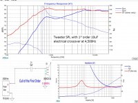
Attached sim of just the SB26CDC-4 dome tweeter on a pyramid baffle with a 1st order 4,500Hz crossover = 10uF capacitor.
=======
If you add a 12db RLC filter at the 690Hz resonance, it has very little effect on the tweeters natural acoustic roll-off, which will combine with the midrange SPL.
Attached sim of just the SB26CDC-4 dome tweeter on a pyramid baffle with a 1st order 4,500Hz crossover = 10uF capacitor.
=======
If you add a 12db RLC filter at the 690Hz resonance, it has very little effect on the tweeters natural acoustic roll-off, which will combine with the midrange SPL.
Attachments
Components will draw current based on the voltage presented according to ohms law. No force feeding involved.
Impedance is a combination of (resistance + reactance). Impedance compensation is simply a way of adding an opposite reactance to counteract the reactance you already have, so that the composite result will behave more like a resistance that doesn't change much with frequency.
Here's the basics as to how: with a resistor, voltage and current are in phase. With an inductor, like in LE, voltage leads current by 90°. In the zobel capacitor, voltage lags current by 90°. If the L and C have reactances of equal magnitude, the voltage across and current through the system as a whole unit will be in phase (i.e., resistive).
The zobel here counteracts the voice coil inductance which would affect your low-pass filtering. It does nothing for the impedance bump around resonance that can affect your high-pass filtering if it's anywhere near fc. To design a passive filter, it's really a necessity to understand impedance. The process may be a worthwhile diversion.
Have fun with your build, that's what this is really all about. A trip with family or good friends can be a great one even if the destination turns out to be foul.
Thanks for a great explanation! So usually one would need the zobel network if the drivers impedance isn't flattish around the crossover point, and in my case in doing 1st order, I need flat impedance to be a least 2 octaves higher than crossover point to be able to keep inductance in check. Otherwise, Zobel network is strongly recommended for the crossover to remain linear(ish). I'll see if I need them thanks!!
Last edited:
Following the Cult of the First Order Rules
Attached sim of just the SB26CDC-4 dome tweeter on a pyramid baffle with a 1st order 4,500Hz crossover = 10uF capacitor.
=======
If you add a 12db RLC filter at the 690Hz resonance, it has very little effect on the tweeters natural acoustic roll-off, which will combine with the midrange SPL.
Your LCR values are not what I was modelling. How did you end up with them? I used this *tested* method and am expecting similair result as per this thread:
Series Notch Filter Designer / Calculator Help
I don't have access to such software yet,
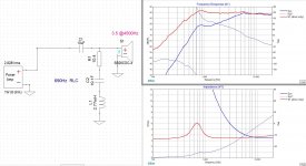
can you model the sb26cdc-4 tweeter with my values in the LCR?
series notch filter
C = 34.44 uF
Inductor
L = 1.55 mH
Resistor
Rc = 5.977450980392158 Ohms
I really need to clear this one up, because this was supposed to work better I suppose.
Last edited:
Following the Cult of the First Order Rules
Attached sim of just the SB26CDC-4 dome tweeter on a pyramid baffle with a 1st order 4,500Hz crossover = 10uF capacitor.
=======
If you add a 12db RLC filter at the 690Hz resonance, it has very little effect on the tweeters natural acoustic roll-off, which will combine with the midrange SPL.
I managed to get Xsim going! where did you get the zma and frd files for the sb26cdc?
can you model the sb26cdc-4 tweeter with my values in the LCR?
series notch filter
C = 34.44 uF
Inductor
L = 1.55 mH
Resistor
Rc = 5.977450980392158 Ohms
attached....
Note the different slopes.
Note notch filters shift phase.
The Cult of the First Order only allows one series C or L (plus resistor) for each driver.
===
My best "bang for the buck" comes from using free S/W crossover plus room equalizer on my PC with a low cost amp/driver. Design and build a clever low diffraction cabinet, purchase quality drivers from China, get a measuring mic, and pound some code.
Attachments
Hi,
Think acoustic slope instead crossover order.
Have fun
Yes, achieve the slope and summation you want, you need to get away from the idea of a specific electrical number of poles in your design.
I let the drivers tell me where they want to be crossed over and I use assymetry all the time in my designs. I never impose or force anything on the design. You have to be flexible.
PROGRESS!!
The weekend was productive Fellaz! I have revamped the system, I will make a post here with all the info and I will EDIT the main post after, to be able to link the models.
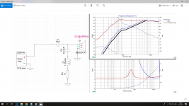
I have mapped all the drivers seperately, and then have combined them into a TRUE 1st order electrical 4-way response graph.
The reasons behind this is that I realised the crossover points between the drivers must be -6db to have a flat response, therefore I have made assymetric crossovers to make sure Im as flat as possible.
The tweeter is already modelled with the series LCR notch in parrallel to the driver, but I havent added the effect of the Zobel impedence equalization networks which are in parallel to the cone drivers.
Thier job is to make sure that the higher frequency zones after the low-pass points to the cone drivers are rolling off at least as intended, if not quicker (meaning 9/db octave instead of 6db/octave). This will even out the bumped kinks you see on the red midwoofer graph, and the black midrange graph past thier low pass points.
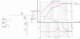
Here are the crossovers:
1). 1" TWEETER
39$ SB26CDC-4 3.4 OHM
1st order high pass CROSSOVER VALUES (7200hz -0, 5400hz -3db, -3800hz -6db)
C1 = 8.66 uF
5.5$ KZK WHITE LINE MKP CAPACITOR (WILL USE 8.2uF)
0.5$ KZK K78-34 BYPASS CAPACITOR (WILL USE 0.02uf)
SERIES NOTCH FILTER PARALLEL TO TWEETER (inductor resistance value has been subtracted from resistor value)
C = 33.93 uF
L = 1.57 mH (0.375 OHM)
Rc = 5.69 Ohms (INDUCTOR RESISTANCE INCLUDED)
2). 3" MIDRANGE
39$ RF-30QY-PRO 7.4 OHM
1st order high/low pass CROSSOVER VALUES: (450hz -6db, 675hz -3db, 900hz -0db / 1800hz -0db, 2700hz -3db, 3600hz -6db)
C1 = 33.65 uF
L1 = 0.44 mH
13$ KZK WHITE LINE MKP CAPACITOR (WILL USE 33uF)
0.5$ KZK K78-34 BYPASS CAPACITOR (WILL USE 0.02uF)
8$ VAJD AUDIO 0,19 Ohm 1,6 mm AIRCORE COPPER INDUCTOR (WILL USE 0,44 mH)
INDEPENDENCE EQUALIZATION ZOBEL CIRCUIT:
C = 11.8 uF
Rc = 9.25 Ohms
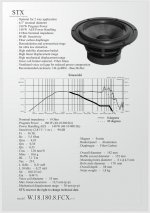
3). 6" MIDWOOFER
44$ STX 180.8 FCX v2 6.2OHM
1st order low pass CROSSOVER VALUES: (337hz -0db, 450hz -3db, -675hz -6db)
L1 = 2.19 mH
16$ Z52-2,2/1,5 TOROIDAL IRON POWDER INDUCTOR 0,11 ohm (WILL USE 2.2mH)
INDEPENDENCE EQUALIZATION ZOBEL CIRCUIT:
C = 4.05 uF
Rc = 8.75 Ohms
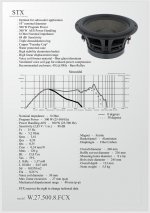
4). 10" WOOFER
82$ STX W.27.500.8 FCX 5.9OHM
1st order low pass CROSSOVER VALUES: (66hz -0db, 100hz -3db, -133hz -6db)
L1 = 9.39 mH
20$ Z52-9,1/1,5 TOROIDAL IRON POWDER INDUCTOR 0,22 ohm (WILL USE 9.1mH)
INDEPENDENCE EQUALIZATION ZOBEL CIRCUIT:
C = 25.19 uF
Rc = 7.38 Ohms
(NOTE: the midrange GREEN plot is for 4 ohm unit, I've subtracted 2.75db)
(COSTS: tweeter setup- 90$ / PAIR CROSSED, midrange setup - 121$ / PAIR CROSSED, midwoofer setup - 120$ / PAIR CROSSED, woofer setup - 204$ / PAIR CROSSED)
TOTAL: 535$ + zobels, using JANTZEN SUPERES.
If I wont have enought money, I will build cabinets but I'll leave the woofers out for some time. I'll loose only the lowest octave.
The weekend was productive Fellaz! I have revamped the system, I will make a post here with all the info and I will EDIT the main post after, to be able to link the models.
I have mapped all the drivers seperately, and then have combined them into a TRUE 1st order electrical 4-way response graph.
The reasons behind this is that I realised the crossover points between the drivers must be -6db to have a flat response, therefore I have made assymetric crossovers to make sure Im as flat as possible.
The tweeter is already modelled with the series LCR notch in parrallel to the driver, but I havent added the effect of the Zobel impedence equalization networks which are in parallel to the cone drivers.
Thier job is to make sure that the higher frequency zones after the low-pass points to the cone drivers are rolling off at least as intended, if not quicker (meaning 9/db octave instead of 6db/octave). This will even out the bumped kinks you see on the red midwoofer graph, and the black midrange graph past thier low pass points.
Here are the crossovers:
1). 1" TWEETER
39$ SB26CDC-4 3.4 OHM
1st order high pass CROSSOVER VALUES (7200hz -0, 5400hz -3db, -3800hz -6db)
C1 = 8.66 uF
5.5$ KZK WHITE LINE MKP CAPACITOR (WILL USE 8.2uF)
0.5$ KZK K78-34 BYPASS CAPACITOR (WILL USE 0.02uf)
SERIES NOTCH FILTER PARALLEL TO TWEETER (inductor resistance value has been subtracted from resistor value)
C = 33.93 uF
L = 1.57 mH (0.375 OHM)
Rc = 5.69 Ohms (INDUCTOR RESISTANCE INCLUDED)
2). 3" MIDRANGE
39$ RF-30QY-PRO 7.4 OHM
1st order high/low pass CROSSOVER VALUES: (450hz -6db, 675hz -3db, 900hz -0db / 1800hz -0db, 2700hz -3db, 3600hz -6db)
C1 = 33.65 uF
L1 = 0.44 mH
13$ KZK WHITE LINE MKP CAPACITOR (WILL USE 33uF)
0.5$ KZK K78-34 BYPASS CAPACITOR (WILL USE 0.02uF)
8$ VAJD AUDIO 0,19 Ohm 1,6 mm AIRCORE COPPER INDUCTOR (WILL USE 0,44 mH)
INDEPENDENCE EQUALIZATION ZOBEL CIRCUIT:
C = 11.8 uF
Rc = 9.25 Ohms
3). 6" MIDWOOFER
44$ STX 180.8 FCX v2 6.2OHM
1st order low pass CROSSOVER VALUES: (337hz -0db, 450hz -3db, -675hz -6db)
L1 = 2.19 mH
16$ Z52-2,2/1,5 TOROIDAL IRON POWDER INDUCTOR 0,11 ohm (WILL USE 2.2mH)
INDEPENDENCE EQUALIZATION ZOBEL CIRCUIT:
C = 4.05 uF
Rc = 8.75 Ohms
4). 10" WOOFER
82$ STX W.27.500.8 FCX 5.9OHM
1st order low pass CROSSOVER VALUES: (66hz -0db, 100hz -3db, -133hz -6db)
L1 = 9.39 mH
20$ Z52-9,1/1,5 TOROIDAL IRON POWDER INDUCTOR 0,22 ohm (WILL USE 9.1mH)
INDEPENDENCE EQUALIZATION ZOBEL CIRCUIT:
C = 25.19 uF
Rc = 7.38 Ohms
(NOTE: the midrange GREEN plot is for 4 ohm unit, I've subtracted 2.75db)
(COSTS: tweeter setup- 90$ / PAIR CROSSED, midrange setup - 121$ / PAIR CROSSED, midwoofer setup - 120$ / PAIR CROSSED, woofer setup - 204$ / PAIR CROSSED)
TOTAL: 535$ + zobels, using JANTZEN SUPERES.
If I wont have enought money, I will build cabinets but I'll leave the woofers out for some time. I'll loose only the lowest octave.
Attachments
-
 FULL SYSTEM ACOUSTIC RESPONSE TO ELECTRICAL FIRST ORDER (ZOBELS NOT MODELLED).png503.5 KB · Views: 675
 -
 SB26CDC 4500 and 5400 -3db 1st order graphs with series NOTCH.png663.2 KB · Views: 234
 -
 RF-30QY-PRO-8-OHM-1st-ORDER--3db(675hz)--3db(2700hz).png734.9 KB · Views: 207
 -
 20W.18.180.8.FCX20rev2-1st order--3db-450hz.jpg180 KB · Views: 207
 -
 W.27.500.8.FCX-1st-order--3db--100hz.jpg179.8 KB · Views: 216
Last edited:
Those of you who love modding and improving things, what's your take? (budget minded please)
Superior-Z or Alumen-Z for tweeter?
HYPEX FUSION 3 WAY AMP and RUN THE MID-TWEETER SECTION ON THE TWEETER CHANNEL?
FA123 OR FA253?
MCA15RCY for Midrange?
4 OHM woofer for less inductor? I didn't plot the impedence yet... being 4-way im already on the limit.
Dual Passive radiators on the woofer for sharper bass, better sound quality and smaller enclosure, like Troels ATELL-3, all while leaving the midwoofer ported for power handling?
How could I have forgotten - ANARCHY MIDWOOFER IN 8 OHMS!! YES
Last edited:
The Anarchy 708 has really low sensitivity.. what a bummer.
Test Bench: Exodus Audio W06-017R “Anarchy” | audioXpress
One could use 2 of them in parallel thought, WTMW configuration, most likely removing the need to the larger 10" woofer, well almost. Im going to model this, for my archive, really good idea and it will make the speaker 3 times as small!!
That would also make all the radiating surfaces aluminium, with closer sonic signiture. The cost also wouldn't increase. (Basically a much diffirent format, almost desktop, with similair properties!!)
Did I tell you I'm gonna print a 4" waveguide for the tweeter to get more out of them, and more importantly align the voice coils on the face plate?
Last edited:
Those of you who love modding and improving things, what's your take? (budget minded please)
Superior-Z or Alumen-Z for tweeter?
HYPEX FUSION 3 WAY AMP and RUN THE MID-TWEETER SECTION ON THE TWEETER CHANNEL?
FA123 OR FA253?
MCA15RCY for Midrange?
4 OHM woofer for less inductor? I didn't plot the impedence yet... being 4-way im already on the limit.
Dual Passive radiators on the woofer for sharper bass, better sound quality and smaller enclosure, like Troels ATELL-3, all while leaving the midwoofer ported for power handling?
How could I have forgotten - ANARCHY MIDWOOFER IN 8 OHMS!! YES
H1262-08 MCA15RCY
Hypex Electronics B.V.
Hypex Electronics B.V.
Humble Homemade Hifi - Cap Test
8" SB20PFC30-8 :: SB Acoustics
ACTUALLY, A PAIR of these in parallel per channel still looks tempting instead of the 10"woofer + 6" midwoofer combo. And CHEAPER. AND BETTER THAN ANARCHY. (82+44 = 126$ for bass setup above, 66 + 66 = 132$ for dual anarchy, 23 + 23 = 46$ for dual SB20PFC !!!!!)
I'll be back with a graph shortly, based on these measurements:
SB Acoustics SB20PFC30-8 | HiFiCompass
I Will be adding 5.5db to this data (+2.75db from impedance going from 8 ohm to 4 ohm, and +2.75db from double radiating area and voice coils)
you can see the response of two drivers in parallel from switching the input signal from 2.83V to 5.6V on HIFI-COMPASS menu in the AXIAL MAGNITUDE FREQUENCY RESPONSE graph posted.
Im gonna model them to be 86-87 db @ 450hz using first order electrical low-pass.
With this pair doing around 93db without attenuation, the math is easy: -6db down @ 450hz, giving me -3db down @ 337hz and -0db down @ 225hz.
0db down @ 225hz is 95db, so thats way too much. Doesnt work.
calculations v2: -9db @ 450hz, -6db @ 337hz, -3db @ 250hz, -0db @ 168hz. Still 95db loud.
two SB20PFC-8 in parrallel wont work, two sb20PFC-4 in series is a waste, so that leaves us with ONE SB20PFC-4")
EVEN SIMPLER, CHEAPER, AND EASIER TO BUILD.
SB Acoustics SB20PFC30-4 | HiFiCompass
using 2.83V this time around.
without too much math, this gives: -0db@300, -3db@450hz, -6db@600hz
Inductor L1 = 1.63 mH will give me this crossover on the SB20PFC-4.
ACTUALLY, A PAIR of these in parallel per channel still looks tempting instead of the 10"woofer + 6" midwoofer combo. And CHEAPER. AND BETTER THAN ANARCHY. (82+44 = 126$ for bass setup above, 66 + 66 = 132$ for dual anarchy, 23 + 23 = 46$ for dual SB20PFC !!!!!)
I'll be back with a graph shortly, based on these measurements:
SB Acoustics SB20PFC30-8 | HiFiCompass
I Will be adding 5.5db to this data (+2.75db from impedance going from 8 ohm to 4 ohm, and +2.75db from double radiating area and voice coils)
you can see the response of two drivers in parallel from switching the input signal from 2.83V to 5.6V on HIFI-COMPASS menu in the AXIAL MAGNITUDE FREQUENCY RESPONSE graph posted.
Im gonna model them to be 86-87 db @ 450hz using first order electrical low-pass.
With this pair doing around 93db without attenuation, the math is easy: -6db down @ 450hz, giving me -3db down @ 337hz and -0db down @ 225hz.
0db down @ 225hz is 95db, so thats way too much. Doesnt work.
calculations v2: -9db @ 450hz, -6db @ 337hz, -3db @ 250hz, -0db @ 168hz. Still 95db loud.
two SB20PFC-8 in parrallel wont work, two sb20PFC-4 in series is a waste, so that leaves us with ONE SB20PFC-4
EVEN SIMPLER, CHEAPER, AND EASIER TO BUILD.
SB Acoustics SB20PFC30-4 | HiFiCompass
using 2.83V this time around.
without too much math, this gives: -0db@300, -3db@450hz, -6db@600hz
Inductor L1 = 1.63 mH will give me this crossover on the SB20PFC-4.
Last edited:
USING THIS SLOPE THE MIDBASS WILL BE CROSSED 3 (THREE) OCTAVES below its APPARENT breakup resonance, and 2.5 (TWO AND A HALF) OCTAVES below its beaming point, in theoritcal-mathematical terms.
OVERALL, this is simpler and more cost effective solution, converting my 4-way to 3-way and lowering amplification demand.
NEGATIVES:
1). LESS BASS
2). MUCH LESS POWER HANDLING (altough i was gonna run the 4-way midbass without high-pass filter, so who knows)
3). The Sb20PFC-4 response rises 3-3.5db between 900 and 1300 hz, making this area acoustically flat with a 1st order electrical. (THIS IS NO PROBLEM, this area IS most important frequency range, and flat is not your enemy, especially having the midrange playing just as flat in this frequency zone. I see this as a successfull model)
NOW I can see how double ANARCHY was able to work in the models, because its 8-10db less sensitive in the low end than the SB20PFC, and has a rising response.
THIS TYPE OF 3 WAY SYSTEM COSTS (WITHOUT CABINETS): 281$
For the masses that HATE CHINA, this allows $ me to upgrade midrange to MCA15RCY, if that RF-30QY-PRO unit doesn't live up to expectations.
Last edited:
So here's a solution to CUT the COSTS, SIZE, AND COMPLEXITY by a FACTOR OF 2:
TO DITCH THE POLISH WOOFER + MIDWOOFER COMBO IN FAVOUR OF:
216cm2 SB20PFC30-4 (3.4-4.6 OHM)
1st order low pass CROSSOVER VALUES: (-0db@300hz, -3db@450hz, -6db@600hz)
Inductor L1 = 1.63 mH will give me this crossover on the SB20PFC-4.
Vajd Audio 1.6 mH* 0.39 Оhm* 1.4 mm COPPER AIRCORE INDUCTOR COIL 12$
INDEPENDENCE CORRECTION ZOBEL: TUNED TO 4.7OHM
C = 20.57 uF
Rc = 5.88 Ohms
Im plotting this out.. give me a sec..
Last edited:
HERE IS THE PLOT FOR THE 1ST ORDER ELECTRICAL 3 WAY
SB20PFC30-4 + RF30-QY-PRO-8 + SB26CDC-4
All three drivers playing the most critical 900-1300hz zone FLAT (AN IN TUNE WITH SYSTEM SENSITIVITY). Daddy Troels G would be proud.
FINALLY IM GETTING RETURNS on my investment of time!!
Here are the crossovers:
TWEETER:
C1 = 8.66 uF + BYPASS
SERIES NOTCH PARALLEL TO TW:
C2 = 33.93 uF
L = 1.57 mH (~0.375 OHM)
R = 5.69 Ohms
MIDRANGE:
C1 = 33.65 uF + BYPASS
L1 = 0.44 mH
MIDWOOFER:
L1 = 1.63 mH
For those of you who cant get KZK WHITELINE / K78-34 capacitors, I would do JANTZEN ALUMEN-Z or SUPERIOR-Z on the tweeter, CLARITY CSA or MUNDORF EVO OIL everywhere else (ZOBELS INCLUDED). For midrange inductors, JANTZEN FOIL-WAX, MUNDORF FOIL OR GOERTZ FOIL. For Midwoofer inductor, 14-15AWG aircore will fit the bill.
ZOBEL IMPEDANCE EQUALISATION RECOMMENDED
FOR MIDRANGE:C = 11.8 uF, Rc = 9.25 Ohms
FOR MIDWOOFER:C = 20.57 uF, Rc = 5.88 Ohms
Alternative midrange (with minor tweaks) as I see it: SEAS MCA15RCY (H1262-08)
Attachments
Last edited:
- Home
- Loudspeakers
- Multi-Way
- Ceramic 4-way 1st ORDER (bang for the buck)