baffle step relates to speaker design with any number of drivers. in regard to pristinely matched sensitivity of drivers, im sure with any number of drivers some amount of resistance applyed is normal. and makes no difference be it 2 way or 4 way or 10 way.
I'm not quite seeing the logic. Which drivers have you chosen and baffle size?
I'm talking about 1st order electrical.
1st order electrical means nothing for your design, its just a way of reaching your target slope which may turn out even 4th order with 1st order electrical. To achieve what you have read on Troel`s website, your acoustic response (so target slope) must be 1st order and I hardly believe you`d do it with a single inductor. Such slopes usually require far more complex crossovers with lots of elements in them.
Better follow the advice already provided by others - start reading about loudspeaker design from the very beginning. A 4 way is an incredibly complex project to get right, focus on 2 ways and then move on.
You cd argue that a 3 way is in some ways easier to design, re baffle step. But the only true dead simple 1st order designs I know about used wide band drivers from Jordan or Bandor, possibly Mark Audio.
Jim Thiel also used 1st order crossovers.. but these werent minimalist.. check out the component count on some of his classic designs
Jim Thiel also used 1st order crossovers.. but these werent minimalist.. check out the component count on some of his classic designs
Jim Thiel also used 1st order crossovers.. but these werent minimalist.. check out the component count on some of his classic designs
1st order loudspeaker needs, well probably custom built drivers. They all have to be very wide band, with flat frequency response, very low inductance or a compensation network to be added, and such hardly exist. Fullrange drivers are among these that can fit well such design, but some like the FE208ES have very limited xmax. But not sure about the massive drive about it when there is a transient perfect 2nd order which will work mostly better.
Thanks for the responses guys!
I have made some changes, and I will be making first order crossovers once I measure the drivers.
Im going for all carbon fiber setup instead of the anodized aluminium:
SB26CDC-4 39$ x 2
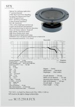
M.15.250.8.FCX 39$ x 2
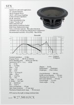
W.18.180.8.FCX_v2 44$ x 2
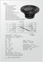
W.27.500.8.FCX 82$ x 2
= 408$ for 2, or 204$ per speaker.
The tweeter will be crossed at 4500hz, the midrange will be crossed with midwoofer @ 500hz and the woofer will be playing full signal strength to 100hz.
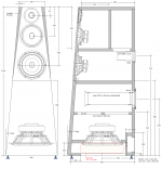
This seems like a substantial upgrade from my initial plans using the same budget. I now have a true 10" carbon fiber bass driver, I have went away from chinese midwoofer and midrange, and I can 100% copy the elipticor 3 cabinets, already in production.
STX have no independence plots, so i'll have to wait.
Thanks guys!
This is a big turn to the plot, take stabs while you can)
I have made some changes, and I will be making first order crossovers once I measure the drivers.
Im going for all carbon fiber setup instead of the anodized aluminium:
SB26CDC-4 39$ x 2
M.15.250.8.FCX 39$ x 2
W.18.180.8.FCX_v2 44$ x 2
W.27.500.8.FCX 82$ x 2
= 408$ for 2, or 204$ per speaker.
The tweeter will be crossed at 4500hz, the midrange will be crossed with midwoofer @ 500hz and the woofer will be playing full signal strength to 100hz.
This seems like a substantial upgrade from my initial plans using the same budget. I now have a true 10" carbon fiber bass driver, I have went away from chinese midwoofer and midrange, and I can 100% copy the elipticor 3 cabinets, already in production.
STX have no independence plots, so i'll have to wait.
Thanks guys!
This is a big turn to the plot, take stabs while you can)
I have made some changes, and I will be making first order crossovers once I measure the drivers
Cult of the First-Order ..... KEEP THE FAITH
")
Just use a simulator with SPL+FRD+ZMA+BAFFLE data before you purchase.
Driver SPL overlaps will cause harmonic distortion and polar distortion which are difficult to model.
-------------
Please post datasheets or measurements for each driver.
P.S. Factor in the China shipping costs.
Ok!! As i understand, I can have a local company like hifi-compass measure the drivers and produce full FRD and ZMA files, having the drivers already mounted in my specific cabinet? Then I use a program to model it, and finally pull the trigger on the crossover values once I got the individual responses figured out.
Ok!! As i understand, I can have a local company like hifi-compass measure the drivers and produce full FRD and ZMA files, having the drivers already mounted in my specific cabinet? Then I use a program to model it, and finally pull the trigger on the crossover values once I got the individual responses figured out.
Not necessarily. You can model for yourself using the factory measurements of the specific drivers using a response tracer software like FRD tool. But be aware, not all driver manufacturers uses the same measurement methods for the datasheets.
The best datasheets for modeling like this is the full 2pi anechoic (e.g. Scan-Speak), this way you can easily add your baffle/box size response to the modeling, but can be done with other datasheets too. SEAS datasheets are nearly useless here, because it uses different baffle sizes for different driver sizes.
Check:
Introduction to designing crossovers without measurement
Last edited:
Thanks again LInesource!
I have posted the theoritical graphs before I make real measurements. I will update the ORIGINAL POST because things have gotten messy. My apologies for this!
Please note that the Tweeter has a series LCR circuit in parrallel to the driver. This eliminated the effect of independence rise @ resonant frequency, making a steeper slope, and allowing better power handling. I was still adviced to add a fuse to the tweeters. Will this negatively impact the sound of the tweeter?
Attachments
-
 SB26CDC-C000-4-graph.jpg119.1 KB · Views: 172
 -
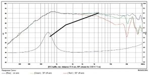
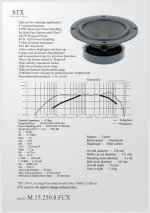 M.15.250.8.FCX. intended 1st order electrical slope.jpg189.5 KB · Views: 167
 -
 20W.18.180.8.FCXrev2 1st order electrical intended slope.jpg179.6 KB · Views: 157
 -
 W.27.500.8.FCX 1st order electrical intended slope.jpg179.4 KB · Views: 151
 -
 Ellipticor-3-cab-large.png154.8 KB · Views: 141
Last edited:
I would like to say that posting on this great forum helps me get going much quicker.
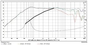
I have made my last post just minutes ago, and by looking at the post above, Im thinking it will be better to lower the -3db symmetrical crossover point between the midrange and tweeter down to 3375hz from 4500hz. Pretty Sure I wont compromise the tweeter this way, all while reducing the effect of breakup (which is visual btw on the graph) and beaming of the rather beefy 95cm2 midrange driver.
Yes Yes Correct?
Last edited:
Like this:
Attachments
-
 SB26CDC-C000-4-graph intended 1st order electrical 3375hz -3db.jpg119.1 KB · Views: 161
 -
 M.15.250.8.FCX. intended 1st order electrical slope 3375hz -3db.jpg188.7 KB · Views: 161
 -
 20W.18.180.8.FCXrev2 1st order electrical intended slope.jpg179.6 KB · Views: 153
 -
 W.27.500.8.FCX 1st order electrical intended slope.jpg179.4 KB · Views: 160
 -
 Ellipticor-3-cab-large.png154.8 KB · Views: 150
Last edited:
^^ Yes thanks, this is given for any system, any drivers, so it doesn't and shouldn't change the world.
A). Exactly for this reason I have closely matched the sensitivities, so the baffle loss/gains wouldn't multiply/scale the diffirences as much.
B). I wont make the crossovers until I measure the Drivers installed in MY baffles. These calculations are simply theoritical targets for now, with small deviations possible to align baffle loss / gain, as well as assymetrical crossover points.
It's great to see some factory frequency responses with your targets, but if you place the drivers on a non-infinite baffle, you get completely different curves.
I agree it MIGHT NOT be a flat frequency response, not even 0.5db, or 1db close. Im prepared already for that. It will colorate and accent SOME narrow frequency ranges, but:
I will still get away with great sound, even if slightly mismatched spl.
I will still get away with the purest passive audio circuit
It will sound amazing because I will use Hi-end parts to assemble those purest passive circuits, like KZK whiteline caps, and Jantzen WAX-FOIL inductors for voicing and Toroidal for the woofers.
And I still have headroom to use L-pads, if you know what I mean.
Last edited:
Guys please school me some more on Zobel (independence correction) circuits. Who's got the know-hows?
I figured out the series LCR, and the Zobels seem so simple Im having second thoughts if Im seeing this correctly.
Impedance Equalization Circuit is simply a capacitor (C) and a resistor (Rc) in series, in parallel with the driver.
Formula:
Re = Driver DC Resistance in Ohms
Le = Driver Inductance in mH
Rc = RE x 1.25
C = LE / (Rc x Rc)
The Zobel basically bypasses a proportion of the signal (outside the flat independence zone to which it is tuned) instead of force feeding a driver in the exponentially rising Independence zone?
Last edited:
Ok!! As i understand, I can have a local company like hifi-compass measure the drivers and produce full FRD and ZMA files, having the drivers already mounted in my specific cabinet? Then I use a program to model it, and finally pull the trigger on the crossover values once I got the individual responses figured out.
You are on the right track. Have them give you good FRD and ZMA and start modeling with WINPCD and a 2 way, please..............
You are on the right track. Have them give you good FRD and ZMA and start modelling* with WINPCD and a 2 way, please..............
Thanks! NA just woke up, should have some more feedback by Monday!
I have a feeling you're talking 2-way because your gut is telling you I will end up with sloped system response, with the bass and midrange being juicier without resistors! (especially talking about the ceramic sb26tweeter with low efficiency of 89.5db)
I have intended for a ~1.5db fade towards higher frequencies past lower treble...
90% of the time this speaker set will be fed with Techno/Progressive music playback, in a decently large room to throw a party. SPL of bass and lower mids fall off quicker than the highs as distance to the speaker increases, in my opinion, based on my past 2 designs in this type of use.
This is a fundamental argument for going 4-way in my view. When I push 7" drivers to fuller excursions, even the female voices get distorted, which is around 700-1300hz. Having a long stroke 10" do the pumping allows less excursion demand on the midwoofer, which in turn enhances sound quality at high power by reducing this excursion induced distortion.
This is also the reason why I decided to upgrade from double stacked SB20PFC 8ohm 8 inchers wired in parallel, as I was sure Id make them distort with their average x-max and cheap motors (with good quality). Having a tweeter not catching up by 1db is much less of a problem, especially crossed high as Im doing)
Personally, I rarely get too much bass on home systems, but walking past a hi-efficiency tweeter at full power isn't nearly as pleasant... if you know where I'm going. Different strokes for different folks...
Last edited:
- Home
- Loudspeakers
- Multi-Way
- Ceramic 4-way 1st ORDER (bang for the buck)