Hi Cori. I totally agree with Don. My first DIY speakers had exactly the same issue as yours even though they were just two ways with a single woofer. They actually sounded good on some music, but were lacking bass and sounding harsh in the treble on other music. I could only listen to them at low volume with most music.
After getting a bit of knowledge over the years, I learned how to use REW, made a measurement mic and mic preamp, and iterated a revised crossover which included adjustments for baffle step losses. In a simple two way, this essentially means shelving down the frequencies from a particular frequency upwards, so these are no 'louder' than the bass frequencies below the 'baffle step frequency'. It also required a notch filter to tame a bump in the woofer response in the voice region; another probable cause of the harshness.
One thing is that I was slacker than many people here, as I only measured the response on axis, where others with do off axis measurements. I did take some shortcuts in my technique. However, it produced results acceptable to me.
Anyway, in a speaker like yours, another way around the baffle step issue is to use the second woofer as a helper woofer to boost the lower frequencies, which means both woofers are not producing exactly the same frequencies.
The starting point is definitely to take a frequency response sweep using something like REW. After a few weeks of tweaking, my old speakers were actually very good and sounded like I'd boosted the bass. This made such a difference, I revamped the cosmetics and started using them on a regular basis. There's quite a bit of info on how to use REW for this kind of thing. The author of the program is quite active on the internet.
Last edited:
@Stuey this is really helpful, and your reflection on your own case was really interesting. Based on your recommendation I've had a read of REW and I'll take care of it. It's quite an interesting process, and it definitely makes sense that a single recording of a given song would yield nowhere near the right information. I'll report back when I have some viable results!
So I used Jaycar CW2194 6.5" (8Ω) drivers instead for each of the originals. I did find exact replacements for the original tweeters, using Tymphany Peerless BC25SC08-04 1" units (at 4Ω) which I ordered from the US. For completeness, this is the plan of the circuit I used:
Thanks for the update.
The drivers + XO + cabinet are treated as a matched set. So different drivers require re-simulation and possibly changes to the XO and port tuning. Give me a day or two and I'll provide a simulation for what you have now. Any changes to the cabinet?
What equipment do you have access to (ie. multi-meter, soundcard+PC, microphone,...) ?
Don, thank you for your comments here, but I want to stress that I didn't intend my post to be an invitation for you to do even more work! Thank you sincerely for your help.
I did not modify the cabinets at all.
As for equipment, I have a multimeter, microphone (I have a Behringer studio condenser mic, for example - REW says it prefers a USB mic, and I have one of those also), and I'll probably take my laptop for the recording work. I can take anything else also, if you recommend it.
No problem, I find this interesting, and its a hobby after all. ")
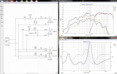
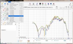
I updated the Xsim model (v6) using the drivers you installed, and the XO as modified. Both drivers only had graphs, that were digitized (via PlotDigitizer) to produced the FRD and ZMA files. A bafflestep curve was also added to the sim as well. The tweeter is horn loaded and is much more sensitive than the driver used in the previous sim. The woofer has an unusual curve, its bumpy, and the LF roll off starts at a fairly high freq.. I did not include port tuning effects on this sim. The good news is that your ears are correct, this speaker is too bright and lacks bass as evident in the upward sloping system FR. It can also be made better. I've attached the design files and a few graphs.
It would be preferred if you were able to measure the speaker "as is" to see if this curve matches the sim. A measurement would confirm the XO mods and provide a better baseline for the next XO tweak.
Attachments
Don this is exceptional work. I really appreciate the time you've taken to model the speakers. I'll need to study the graphs further to understand them, but it looks like things start falling off below about 200Hz, would that be right? If so, I think this would accord with what I heard the last time I experienced them, where, in one sound clip, the bass seemed to "sheer off" into nothing, like the driver hit a lower limit and wouldn't respond below that floor. It's reassuring to know that my ears are hearing things acceptably!
I'm really looking forward to taking the measurements now! It's pretty exciting to know that I might be able to collect some data to see if they respond in reality as they do in the simulation here.
I'm really looking forward to taking the measurements now! It's pretty exciting to know that I might be able to collect some data to see if they respond in reality as they do in the simulation here.
OK, at last I have completed the REW measurements. I calibrated everything first, then took four measurements with a USB microphone. The first three measurements were 0 degrees from centre axis (i.e., between both speakers), about 2m back, and the fourth about 2.5m back (roughly). It was my first ever measurement, and I hope I did it correctly!
Attachments
@Cori, thanks for posting those measurements. Just one item that needs to be checked before we dive into them.
Is it possible (with your setup) to do a PC cable loopback test (connect the PC soundcard's Line out to Line in) then run REW. PC's are notorious for fiddling with the audio processing to "improve" your experience. The REW test result needs to be flat, to confirm that all PC audio processing is disabled.
I'm assuming the speaker test setup is PC (Laptop) to Amplifier to speakers to USB mic. Some amplifiers (HT) may also have additional processing that needs to be turned off during the speaker measurements.
Last edited:
Both woofers use same coil value and padded with 2.2 ohms resistor?
Why?
Or im I just confused what crossover schematic im supposed to be seeing.
Dont even see components shown in factory photos.
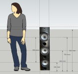
Center to center of woofers very far apart
So needs a lot of help.
Padding the woofers is great way to have no bass.
Plus share same bandwidth. Lower woofer should be used
at lower crossover point.
Mounting speakers miles apart with 1st order.
no mid
Would be little work to see a accurate sim.
The large center to center space needs to be accounted for.
The mid is vented so a accurate impedance model might be needed.
Since the lower crossover might be in the impedance peaks.
Maybe others should be aware of the center to center spacing
and skinny baffle response your up against.

S
Why?
Or im I just confused what crossover schematic im supposed to be seeing.
Dont even see components shown in factory photos.
Center to center of woofers very far apart
So needs a lot of help.
Padding the woofers is great way to have no bass.
Plus share same bandwidth. Lower woofer should be used
at lower crossover point.
Mounting speakers miles apart with 1st order.
no mid
Would be little work to see a accurate sim.
The large center to center space needs to be accounted for.
The mid is vented so a accurate impedance model might be needed.
Since the lower crossover might be in the impedance peaks.
Maybe others should be aware of the center to center spacing
and skinny baffle response your up against.
S
Last edited:
OK, at last I have completed the REW measurements. I calibrated everything first, then took four measurements with a USB microphone. The first three measurements were 0 degrees from centre axis (i.e., between both speakers), about 2m back, and the fourth about 2.5m back (roughly). It was my first ever measurement, and I hope I did it correctly!
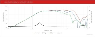
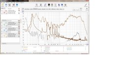
Some interpretation of the data provided (I used REW 5.30.2). All the plots show the same issues. What USB mic? and did it have a cal file?
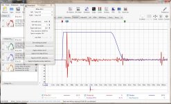
The REW data needs to be windowed to remove boundary reflections from the measurement. The "IR windowed" plots show the primary event [ t=0 to 0.5ms ] and secondary events at [ t = 2ms, 5.5ms, 9.5ms ] caused by reflections. Setting the IR window to 6ms will remove most of these reflections from the measurement. Not obvious here, but the longer the window, the lower the measured freq. There is a practical window limit of course, based on the room size and furniture. Lower freqs can also be measured using nearfield if needed. Sound travels approx 1m in 3ms so you can ballpark where those reflections are coming from and adjust placement or window them out.
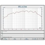
The data always contains some noise and that can be reduced using windowing, then smoothing to help see the fundamental issues a bit more clearly. The "SPL windowed and smoothed" graph shows the mid bass sag and the high output from the horn tweeter.
The midbass sag problem is also evident in the "THD and Noise" plot. There could be a number of issues causing this, like, XO wiring problem, reversed midrange driver, unintended HT amp processing, unintended PC soundcard processing, etc. The tweeter section looks like its working OK but the sensitivity will need to be attenuated to the level of the woofers+midrange when they're fixed.
Attachments
Can only get rough estimate.
But visually Center to Center for top and bottom 6.5"
close to 550mm
So depending on crossover wouldn't expect
it to do much else than
cancel upper response of the 6.5"
So lower woofer needs to crossed very low.
Would very much be connected to the largest
inductor on that low frequency board.
Otherwise it would cancel all the upper range
of the midrange 6.5" mounted a zillion miles
away.
Or from the response looks like a phase cancellation
so polarity might be wrong on the second woofer
up or the high mounted midrange.
Attachments
Last edited:
- Home
- Loudspeakers
- Multi-Way
- Refurbishing PSB Image 6Ts - sanity check!