Sadly I don't have the tools to simulate the crossover using the baffle and bass reflex/in cabinet responses (I am using VituixCAD right now); I am stuck with the infinite SPL provided by SB Acoustics so I can't actually give you any feedback about your changes. And if I amy ask what software are you using?
About the tweeter SPL, I am pretty sure my dad prefers a more present high end so I guess a 0,75 or 1 Ohm resistor will be enough but then this is going to be a subjective matter and like you said I can tune it with a combination of resistors later when the cabinet is done.
About the tweeter SPL, I am pretty sure my dad prefers a more present high end so I guess a 0,75 or 1 Ohm resistor will be enough but then this is going to be a subjective matter and like you said I can tune it with a combination of resistors later when the cabinet is done.
I was able to run a simulation using the Boxsim software (which I am still learning to use properly and I can't properly design your front baffle design, I am stuck at 45 degree angles for the edges and I used a 2x2 cm value for all the sides).
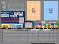
After setting a few things up I was able to run the optimization script on the XO network and this is what it outputted using the available items from the store I will buy from:

How does it look on your simulator?
Considering that the cost of the crossover is around 95 euros for each speakr I better pick up the best solution here and I am also curious to compare the results.
After setting a few things up I was able to run the optimization script on the XO network and this is what it outputted using the available items from the store I will buy from:
How does it look on your simulator?
Considering that the cost of the crossover is around 95 euros for each speakr I better pick up the best solution here and I am also curious to compare the results.
A crossover optimizer which only uses the driver impedance cannot adjust for irregular driver SPL effects like cone break-up, rising SPL at high frequency from beaming, baffle edge effects, and baffle-step effects from the low frequency transition from 2Pi -> 4Pi room radiation.
YOU COULD:
1) Start construction of the cabinets now
---do not route baffle speaker holes until you have actual drivers
2) Continue education in simulation
--- Use FPGraphTracer to import into Vituix the on-baffle SPL measurement data from SBAcoustics 61-NAC as an FRD file
3) Continue to request support on diyAudio website until you feel confident in $$ purchase
--- will not affect schedule until cabinets are completed
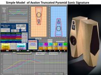
P.S. Your optimizer crossover circuit shows:
1) +SPL bump from 200-2000Hz created by the baffle effects
2) no low frequency baffle step compensation
3) does not adquately attenuate the metal cone break-up effects
4) the midbass SPL does not closely follow the ideal LR4 curve because it does not factor in the imperfect rising high frequency SPL from the driver
P.S. You still need to decide if you want a crossover optimized for against the wall placement, or a more common circuit which includes modest bass baffle step compensation.
YOU COULD:
1) Start construction of the cabinets now
---do not route baffle speaker holes until you have actual drivers
2) Continue education in simulation
--- Use FPGraphTracer to import into Vituix the on-baffle SPL measurement data from SBAcoustics 61-NAC as an FRD file
3) Continue to request support on diyAudio website until you feel confident in $$ purchase
--- will not affect schedule until cabinets are completed
P.S. Your optimizer crossover circuit shows:
1) +SPL bump from 200-2000Hz created by the baffle effects
2) no low frequency baffle step compensation
3) does not adquately attenuate the metal cone break-up effects
4) the midbass SPL does not closely follow the ideal LR4 curve because it does not factor in the imperfect rising high frequency SPL from the driver
P.S. You still need to decide if you want a crossover optimized for against the wall placement, or a more common circuit which includes modest bass baffle step compensation.
Thanks for the feedback and as you can see I am still learning about a lot of stuff.
There is a but tho. I am already using the frequencies responses of the drivers; I've traced them with VituixCAD (and I guess SPLs are on an "infinite baffle"), as you suggested, and I've been using them to run the simulations since your first crossover option.
I am even using LspCAD 6 now with the advanced options on (meaning 19L bass reflex cabinet with your port's sizes and diffractions of the speakers and bass reflex port on and placing them based on your design) and the SPL response curve is kinda weird; it goes linearly up ending with 20kHz over 10db the average (and in this case even if weird in its way the crossover from BoxSim has the least "wobbling" response making the "/"-shaped curve the most linear).
On the could list:
1) That is the easy part and I will as soon as the weather gets a little warmer (I can't use the garage right now, it's packed ahah) EDIT: what about the inside bracing? Do you have any design to show? Can there be none and use only damping material? Or it is important for cabinet solidity?;
2) I'll keep experimenting indeed;
3) here I am and so far I am only sure on the drivers to buy; these SB Acoustics.
Abotu the PS list.
1) which is the opposite that I get running your crossovers on my simulations but again in many I can't add bass reflex and diffaction responses.
2) is that important? I mean is the size of the baffle this wide to have bumps in the low frequencies? I've read the paper and it seems the higher frequencies are more subject to this, because of their nature (higher frequencies, closer the audio beams).
3) I guess this comes from experience.
4) I don't know about it because even if it doesn't follow the ideal LR4 curve it doesn't mean it's bad for this driver but again I am just talking looking at simulated datas and I am pretty sure you have more experience than me.
And least but not least.
As I said the speakers will be close to the wall; let's say 25 cm away from the back wall and the left one will be close to the side wall (25 cm, maybe less honestly) plus there is a furniture at 94 cm from the top of TV furniture on where the speakers will be placed.
So a crossover optimized for against the wall placement is the only option and it makes my simulations even more harder.
PS: I own a Umik-1 and I will gladly use it to measure the speakers and make XO adjustments but considering the costs of the crossover itself the less I will spend after for the tuning, the better.
Last edited:
Another post, sorry.
And so what if I make the cabinets, buy the drivers and test them into the cabinet and then build the crossover using the measurentes I will take with the Umik-1 with the speakers in their listening position? Seems the best and smartest move here, right?
And so what if I make the cabinets, buy the drivers and test them into the cabinet and then build the crossover using the measurentes I will take with the Umik-1 with the speakers in their listening position? Seems the best and smartest move here, right?
Well even if it is cool to play with such stuff and monkeys are everywhere (indeed I have bought the Umik-1 to measured my box design for the Markaudio CHR70 and tune it with Equalizer APO since I use them on my desktop PC) I prefer not to spend any more money on gear to test loudspeakers.
My idea is to singularly measure the drivers response (with the mic set on tweeter center height at maybe 1 meter, still wondering on this) but with them mounted in the cabinet and the cabinet placed in the listening position.
Can't I use the plots from REW or any other analyzing audio software to find out how to time align them properly?
PS: I just ordered the drivers and the materials for the cabinet; I'll buy XO materials after I finish the build.
Last edited:
You can make the cabinet so the front baffle is removable to try different driver placement - often moving tweeter off center helps smoothing out peaks and dips and you don't have to rely only on crossover to smooth out the freq response. For most 4ohm 6" SB, the first coil in x-o is around 1mH, I would get a bigger value and unwind just in case, or make one with two values, say 1 and 1.2mH to have some flexibility in tonal adjustment. I use around 1.6mH for free standing monito with 17NRX-4, 50cm from back and 1.5m from side walls. Of course you will have to attenuate tweeter accordingly, with SBs less than 0.5dB here and there makes quite a difference as they are very transparent speakers. Also don't take as final 100% what the simulator tells you, experiment a bit around the values - use your ears as final judge, I was very surprised that being a bit off produced more satisfying sound.
@pliedtka
I think I am gonna try the Gravesen front design from his SBA61-NAC build first to address the polar center of the speaker (the loudspeakers will be placed on the TV furniture making the tweeter face a very low point, and maybe I'll just angle the front baffle of the speaker properly to address the issues even better, I have stil some time to virtually experiment) but using a bigger volume cabinet if it's worth it (SB Acoustics suggests a 17L vented box with port tuned at 35Hz amd using the Illuminator dimensions and with everything ion place I guess I am there with the net liters).
About the crossover, thank you for the tip and so far every simulations run never suggested a value over 1,5mH if I recall so we agree on that. By the way this midwoofer is a bad boy and have a very difficult SPL to address but maybe I found the trick, looking at Gravesen XO network: use a resistor (between plus and minus, sorry I don't know the proper term, maybe short?) after the first inductance to attenuate the high frequencies even further.
@Qts
Thank you for the suggestion but I guess I am going to stick with the front baffle design/experimentation to address these issues. I already have a decent starting point which is, as said before, Gravesen's design.
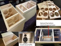
what about the inside bracing? Do you have any design to show?
One example cabinet construction:
1) Well ventilated horizontal braces.
--Typically cut with router using quarter round bit and circle cut jig
-- Hand saber saw can cut 4-square windows brace
2) Optional interlocking top-to-bottom wood stick brace
3) Fiberglass or wool on sides and back to absorb speaker rear wave
-- Extra loose fiberglass directly behind midwoofer
4) Bevel cuts on front baffle reduce edge distortion
--Avalon Compas double bevel top style functional and attractive
Attachments
How important is the total area of the holes? I know it can works as a coupling chamber in a TL (or in a dual bass reflex load design) to cut-off some frequencies for the next volume (if I kinda understood it correctly).
Should I just make a bracee with two rectangle-shaped holes as big as I can to make it strong enough or do I have to focus on the total open area also?
Gravesen is using two 130mm holes on the braces for his SB61-NAC build (and in many other builds with relatively small cabinet volumes) so I can use it as a strating point but I am also interested in your opinion.
I am still wondering about the front baffle design and considering the low position of the speakers I am inclined to make a slope design for the front of the speakers. I'll have some good CAD time now.
I second what Line Source wrote. Cabinet design alla Avalon style with more bevel, with some rounding, around tweeter than woofer for better stereo image. Braces - you can make 4-6 smaller square openings in the brace, but have 25-30mm of material between the edge and opening for the brace to be effective. I think Troels did his round because they were easier to cut. As for the slopped baffle to align drivers acoustics center, it depends on what kind of filters and crossover frequency you choose - sometimes it works in your favour, sometimes it doesn't, and if it doesn't follow LR24 transfer function, doesn't have full reverse dip, it's asymmetrical, doesn't mean it will not work - your ears are the judge, lot's of fun and sometimes a bit of luck make them sing, no hard to follow rules here.
@pliedtka
I will figure out some design that can fit my needs and visual style. I am into a somehow mesh-up of both the Avalon style and what Gravesen did.
And I agree on what you say: at the end it is about what it makes me happy to listen to and not about what the measurements say.
I will figure out some design that can fit my needs and visual style. I am into a somehow mesh-up of both the Avalon style and what Gravesen did.
And I agree on what you say: at the end it is about what it makes me happy to listen to and not about what the measurements say.
@davecandialex
There aren't any tweeter wave-guides in the store I am buying from and I am not sure which one to get (if I can find any) and how to mount it on the tweeter (considering that I have to remove its front part first).
I'll try to use different baffle designs and measure and analyze them to mitigate the reflexion/diffraction problems.
I am going to try the simple Gravesen design first on his SB-61NAC build and then start from there.
Qts, how do like the SB26ADC tweeter. I want to try alu dome after many years, but I'm afraid it will be another one I can't stand. I use 29RDCN in my build, it's OK, but doesn't like to be crossed below 2.5k-3k, 18dB acoustic, as it starts to 'scream'. I need something which I can use lower than 2kHz w/o the waveguide. But I will ask, how is SB29ADC in the waveguide, anyway.
Last edited:
")
I'm back!
I've made my own cabinet, about 19L net, and I made some measurements.
Here are the graphs.


Microphone set 50cm away from tweeter and on axis. Damping with 1cm muhwolle on sides, top and bottom while 2 cm polyester damp (200gr/sqm) on the back.
I've used the whole lenght of the port (which is 143mm) but it looks like I need to cut it shorter.
Any advise and what about the possible crossover?
I have the REW files if somone wants to play with them.
I've made my own cabinet, about 19L net, and I made some measurements.
Here are the graphs.
Microphone set 50cm away from tweeter and on axis. Damping with 1cm muhwolle on sides, top and bottom while 2 cm polyester damp (200gr/sqm) on the back.
I've used the whole lenght of the port (which is 143mm) but it looks like I need to cut it shorter.
Any advise and what about the possible crossover?
I have the REW files if somone wants to play with them.
- Status
- This old topic is closed. If you want to reopen this topic, contact a moderator using the "Report Post" button.
- Home
- Loudspeakers
- Multi-Way
- DIY 2-way design for a bookshelf