I was in the same position a few years ago, the only drivers I could get were car speakers with no Thiele parameters what so ever, now I can order Dayton drivers and others from amazon. I accidentally found a great way of voicing speakers that I would recommend, play some music through them and record it ( some mobile phones are sufficient for this ) then play the recording back through the speakers, this will double ( or possibly quadruple ) this errors making the far more audible. Also listen to some test tones to here what certain frequencies sound like, or get a graphic equaliser so you can see what dipping or increasing different frequencies does to the sound.Hello friends.
This is a topic that is dear to me. So is "making silk purse from sow's ear" thread.
Where I live, there is very little options for reasonably-priced, decent drivers with complete T/S parameters. No Dayton Audio equivalent here! Most of the beginner DIY-ers just make a box that looks cool and tweak by ear.
Over the years, I've acquired Dayton USB measurement mic, REW, and recently I've started learning to use impedance measurement functions of REW, as well as tweaking crossover designs in XSim. I feel like I'm heading in the right directions, and I want to keep learning.
One question from me please: speaking of "designing speaker from scratch", is there a general guidelines of "voicing" your own designs? For example, boost around xx frequency will emphasize sibilance, cut around xx frequency will give the impression of ... etc.
I know we generally aim for the flattest response, but this question comes to mind when doing simulations on XSim, sometimes we have to compromise a little bit here and there, considering component values, whether it's worth it to add a notch filter or not, etc.
Also, is there a thread where we just share pictures of our build and the final project? Thank you!
Tom Danley has been the one to talk about it most around here. This is but one time - Beyond the Ariel
Scroll down the post to the mention of 'generation loss'.
Scroll down the post to the mention of 'generation loss'.
This was how it looked in mine.There is conflicting information in all of this.
Designers of vented enclosures note that if you damp so effectively, it also takes a little of the sting out of the main (wanted, bass-reflex style) lowest frequency box resonance.. and now it's compromise time regarding how much to use and how.
So along comes the myth that ported boxes should have only a thin lining of damping material. It is often missed that the higher order (higher frequency, unwanted, standing wave style) box resonances still occur in vented boxes as well.
In conclusion, I think it comes down to your damping strategy in any case.
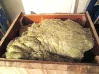
I ended up using lots of rockwool cos the local hardware shop had loads of it on discount cheap...
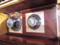
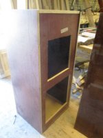
You can see how the cab has been constructed first with a front with 2 templates in (large square cut outs), then a detachable front which is bolted into place over the top of the template.
I have never seen that done before, and it has carefully made chamfers all over to try to mitigate reflections.
The ports are just above the lower (15") driver, of different lengths to cater for the different sizes of driver (12 and 15")
After that,
I have an awful lot of explaining to do.

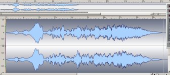
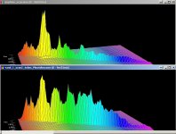
Basically I used the same studio microphone for tests to measure scans 20hz-20khz over a 10 sec test.
distance was less than 1m to try to reduce room effects.
It was possible to measure 2 "hi end" speakers in the local shop.
Vandersteen 2cx including a back to back test using SINGLE and genuine Biwire arrangements.
I also tested Amphion which turned out not to be 8ohms (very much) but more like 4 most of the time.
Matching the speaker to 4 ohm taps rather than 8, therefore seemed to make little difference to SPL but changed output spectra recorded on the DAW.
Then the Vand speaker of course, which had a flatter response curve...
(the bi wire back to back test with seperate taps on the output transformer proved beyond doubt, bi wiring changes the spectra).
The KT8 amps used were 50W amps which we know have quite a flat output across the entire audio spectrum (known entities).
I don't think they are vastly different from the home studio system.
We used the same methodology to test the AMPHION speaker (Finland).
Amphion think a lot of themselves, but we proved it suffered a devastating "boom" period, and apart from that has little treble and poor bass. As you can see compared direct with the Vand.
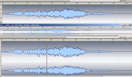
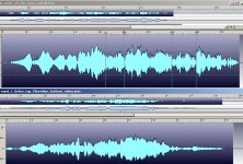
The Vandersteen type test was repeated back at my studio, AFTER I had added the Lomo horn, so we could directly compare the spectra seen by the same mics at close range (but in a different room with wood floor and good damping)
Ahum.
Well this is a quite valid test which demonstrates the horn has tremendous performance right off to 20khz.
The vandersteen had at least -10dB at the bottom end and pretty much the same at the top.
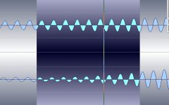
Another graph shows the principal consideration.
Getting linearity at 40hz.
Below this you can clearly see distortion in the recorded waveform, in the "monster" but of course the ear is relatively insensitive to this.
why bi and tri wiring???
Because being as the woofers are connected to totally different taps/windings on the transformer, there can be zero interraction between any drivers no matter what mix of frequencies is going out the amp.
This trick is almost impossible to do, on any other amplifier I know of, people always end up using 2 or 4 or 6, which of course produce drastically different results, especially if the amps are not identical....
The fascinating thing was seeing it actually proven on part windings when feeding the HF end of the vandersteen seperately from the LF end with 2 seperate harnesses...

Attachments
-
 template_front.jpg83.5 KB · Views: 181
 -
 huge_speaker_1059.jpg73.8 KB · Views: 179
 -
 clean_40hz_new_speaker.jpg102.8 KB · Views: 170
 -
 amphion_BOOM.jpg182.9 KB · Views: 170
 -
 volta_scans_13_02_2020.jpg195.9 KB · Views: 167
 -
 better_copy_of_loads_compared_vandersteen.jpg239 KB · Views: 43
 -
 lomo_trace_19_feb_full_scan_v_vandersteen.jpg288.3 KB · Views: 43
 -
 rock_1370.jpg112 KB · Views: 62
Thanks Allen. That pushed me towards the ported box again.In conclusion, I think it comes down to your damping strategy in any case.
I share my findings below, please feel free to share your thoughts, Allen.Thanks Tony. I've read your thread all the way through. Nice drivers from SB Acoustics, I see.Here is a small BR speaker I made SB acoustics SB12MNRX25-4 "full range" Build thread These actually sound surprisingly good.
If you don't care about the low bass output because you are going to crossover to a sub anyway, I would definitely change the tuning to something a bit more flat than your winisd plots show. The transient respsonse should be a lot better too.
Tony.
Thanks for the pointer. I ran all the different ported alignment on WinISD, and it seems for this driver, the flattest I can get is actually close to EBS3 alignment.
Unfortunately (and sorry for not mentioning earlier) I'm stuck with 2 liter net volume max, since the box is halfway built. Counting for the port and driver displacement, I got a net 1.8 liter. With the box dims and this tuning, I'm stuck with approx. 1 inch port ID.
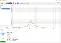
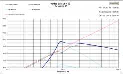
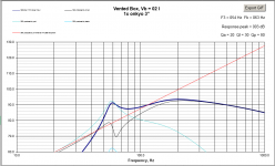
Red= 2 liter volume, 72Hz tuning, 26mm port ID
Green= 1.8 liter volume, 63Hz tuning, 22mm port ID
Any comments on the frequency response and air velocity for the green graphs? Thank you again.
Thanks my friend. Recently, I have built the rig and learned how to measure impedance and with that, measure T/S parameters. I appreciate you sharing your tips, I will keep that in mind, perhaps sharing with others who may be in a similar situation.I was in the same position a few years ago, the only drivers I could get were car speakers with no Thiele parameters what so ever.
Attachments
I just wanted to point out the transformer used for supplying the studio array is highly unusual.
It has 3 seperate harnesses:-
25V CT winding then a 16ohm tacked on the end.
I put a Dayton choke on one end and it feeds the LF, meanwhile the 25V CT bits are fed straight back into the cathode circuits to give NFB.
There is very little loop NFB as a result which means quite limited phase shift/instability.
A 70V CT winding (ie 2 x 35V) or if you like 24ohm x 2.
This feeds the mid range via a typical crossover, and filters off the LF.
Finally a 115V tap is tacked on the end of the 70V winding giving in effect a 45V winding from 70-115V.
This feeds a cap which goes to the HF - horn on a seperate harness.
We have had many interesting discussions about this, due to the way transformers behave when the windings are loaded, compared with them unloaded, as well as stray capacitances and HF THD.
No proper simulation is really possible, because of the complex interractions taking place it appears.
Jo Brosky did come up with exactly this idea a few years back, albeit without access to such complex wound high quality transformers being run into inductive loads with very limited loop NFB.
However when the acid tests took place, we struggled to find any place where the waveform fed back either directly from the output or from the studio microphones deviated from anything other than excellent linearity.
It's basically an active+passive crossover hybrid, which is an interesting aside to the speaker debate.
Interractions between speaker and amplifier are yet another one of those "black art areas" which I could prove are genuinely affected by wiring harness configuration.
Sibilance 4k to 10k. Tinny 1k to 2k. Honk is 500 to 800. Fullness is 250 to 500. Warmth is 125 to 250. Boom or punch is 95 to 160. Rumble is 25 to 40. Chest thump is 20 to 35.Hello friends.
This is a topic that is dear to me. So is "making silk purse from sow's ear" thread.
Where I live, there is very little options for reasonably-priced, decent drivers with complete T/S parameters. No Dayton Audio equivalent here! Most of the beginner DIY-ers just make a box that looks cool and tweak by ear.
Over the years, I've acquired Dayton USB measurement mic, REW, and recently I've started learning to use impedance measurement functions of REW, as well as tweaking crossover designs in XSim. I feel like I'm heading in the right directions, and I want to keep learning.
One question from me please: speaking of "designing speaker from scratch", is there a general guidelines of "voicing" your own designs? For example, boost around xx frequency will emphasize sibilance, cut around xx frequency will give the impression of ... etc.
I know we generally aim for the flattest response, but this question comes to mind when doing simulations on XSim, sometimes we have to compromise a little bit here and there, considering component values, whether it's worth it to add a notch filter or not, etc.
Also, is there a thread where we just share pictures of our build and the final project? Thank you!
 cracked case!
 Johnathan, don't be scared to try arbitary alignments, you don't have to use one of the established ones. They are all on a continuum really, and some other tuning may work better with your particular driver. Since your volume is already fixed, try moving your tuning frequency up. keep increasing it and see what it does to the response curve. As you are going to be crossing above 100Hz you have a fair bit of room to play with.
Can you post the T/S params of the driver?
Tony.
Thank you dave for sharing.Except for the sealed sim, those are pretty ugly curves.
One of my prime rules for any BR sim is that the 1st derivative of the FR curve should cross zero once at most.
dave
Since I'm not an English native speaker, I'm afraid I have to ask: which area is the "1st derivative of the FR curve should"? Is it the bottom end below 100Hz where it forms a 'tail'? Perhaps you have a graph of a tuning that you prefer, that would be most helpful.
Thanks again, dave.
Awesome!! Thanks so much, cracked case! This is going to my notepad for speaker buildingSibilance 4k to 10k. Tinny 1k to 2k. Honk is 500 to 800. Fullness is 250 to 500. Warmth is 125 to 250. Boom or punch is 95 to 160. Rumble is 25 to 40. Chest thump is 20 to 35.
Many thanks Tony, will try raising the tuning frequency. So far I was looking for the lowest F3, but soon I learned that it's not the ideal objective in this case. Here's the T/S parameters, please have a go at itSince your volume is already fixed, try moving your tuning frequency up. keep increasing it and see what it does to the response curve. As you are going to be crossing above 100Hz you have a fair bit of room to play with.
Can you post the T/S params of the driver?
Tony.
Zmin 4.18 ohm
fmin 309 Hz
f3 771 Hz
Le(f3) 0.738 mH
Motional impedance parameters
RES 30.18 ohm
LCES 4.690 mH
CMES 329.4 uF
RAMS 30175.175 mohm
Blocked impedance parameters
RDC 3.73 ohm
dR 0.00 ohm
Re 3.73 ohm
Leb 62.5 uH
Le 1.103 mH
Rss 57.8 ohm
Ke 0.1579 S-H
Thiele-Small parameters
fs 128.1 Hz
Qms 5.440
Qes 0.988
Qts 0.836
Fts 153.1
Mms 5.59 g
Cms 0.276 mm/N
Rms 0.826 kg/s
Vas 0.36 litres
Bl 4.119 Tm
Eta 0.07 %
Lp (1W/1m) 80.86 dB
Dd 6.20 cm
Sd 30.2 cm^2
Many thanks, Tony and everybody!
Ported boxes are often used to push down in frequency. If you push too hard you get an uneven response that can be troublesome. Look at group delay in the sim and try to be gentle. This should look better with a smooth response. You may not reach the lowest frequency, but the upper bass is more important and you can always add a sub or two.Thanks Allen. That pushed me towards the ported box again.
Since I'm not an English native speaker, I'm afraid I have to ask: which area is the "1st derivative of the FR curve should"?
It is in the universal language of math, so it matters not what your native language is :^)
The easiest way i can think of translating this is that the curve should only have at max 1 place where the curve goes from movin gup to moving down in the LF. You have 2 in each of your sims and i have found that designs not following this rule are the ones that give BR a bad name.
dave
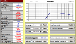
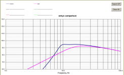
OK I had a play in unibox, it's not easy getting a good FR curve with this driver. Totally ignoring convention, this is what I came up with. Not sure how the heavy fill will go in reality, maybe will make it a bit more aperiodic than vented, but it was the only thing that seemed to work to get rid of the hump at the end. May want to go even a bit higher tuning freq, perhaps 100Hz to get rid of that slight dip around 120Hz.
Should be able to handle about 10W without issue (assuming the 3mm x-max I guessed is reasonable).
edit: added comparison of sealed vs vented.
Tony.
Should be able to handle about 10W without issue (assuming the 3mm x-max I guessed is reasonable).
edit: added comparison of sealed vs vented.
Tony.
Attachments
Last edited:
Thank you dave for this point, I will keep in mind for my speaker builds!The easiest way i can think of translating this is that the curve should only have at max 1 place where the curve goes from movin gup to moving down in the LF.
dave
OK I had a play in unibox, it's not easy getting a good FR curve with this driver. Totally ignoring convention, this is what I came up with.
Tony.
Tony, thanks a lot for taking the time to simulate in unibox. That does look like a nice tuning, I think I will go ahead with that.
So volume is 2L, port ID 2.61cm, port length is 7.55cm, line the inner walls and heavy stuffing?
I've tried 2L/90Hz in WinISD before, but it resulted in an unsightly hump. Is there a known discrepancy between the two softwares?
Thank you again for taking me through this process.
I hope I didn't lead you to feel that a box needs to be heavily stuffed. The only time you need that is when you are trying to damp the fundamental (wanted) bass resonance, such as in lieu of making your box larger. This is a popular move with closed boxes.
20% of each dimension has been shown to work sufficiently on average, against box modes, when using an effective damping material such as fibreglass or rockwool. 40% can be better for modes, but this is the compromise range.
20% of each dimension has been shown to work sufficiently on average, against box modes, when using an effective damping material such as fibreglass or rockwool. 40% can be better for modes, but this is the compromise range.
That's probably more come from me Allen, just a happy coincidence I suspect
Jonathan, the port is actually 3cm the 2.61 is what unibox says is the minimum (based on the 10W I put as input)
On the difference between unibox and winisd there are quite a few things you can tweak in unibox, it is possible that some of the parameters are different to what you have in winisd. I never really got into winisd, I've relied on unibox. Can you specify stuffing in winisd for a ported enclosure?
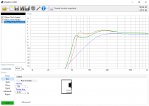
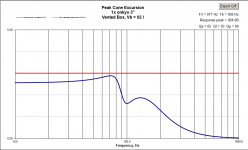
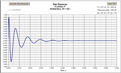
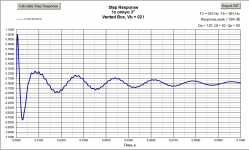
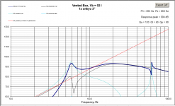
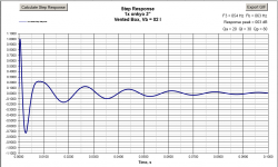
Below is how it sims in unibox with 1.8L and 63Hz which is what showed on your last winisd sim. This is with no fill and no leaks. Note the step response! It shows both the much worse transient response and also the port resonance. edit: actually I see you had a 2.2cm port diameter, that completely removes the port resonance, but will also probably get chuffing if you push it. I added the sims with the 2.2cm port as the 3cm port ones are pretty ugly in comparison! oh and the 2.2cm ones also have walls covered, not bare.
The third is the 2L 95Hz tuning but with walls covered rather than heavy fill.
Tony.
Jonathan, the port is actually 3cm the 2.61 is what unibox says is the minimum (based on the 10W I put as input)
On the difference between unibox and winisd there are quite a few things you can tweak in unibox, it is possible that some of the parameters are different to what you have in winisd. I never really got into winisd, I've relied on unibox. Can you specify stuffing in winisd for a ported enclosure?
Below is how it sims in unibox with 1.8L and 63Hz which is what showed on your last winisd sim. This is with no fill and no leaks. Note the step response! It shows both the much worse transient response and also the port resonance. edit: actually I see you had a 2.2cm port diameter, that completely removes the port resonance, but will also probably get chuffing if you push it. I added the sims with the 2.2cm port as the 3cm port ones are pretty ugly in comparison!
oh and the 2.2cm ones also have walls covered, not bare. The third is the 2L 95Hz tuning but with walls covered rather than heavy fill.
Tony.
Attachments
Last edited:
Hi Allen: Yes that came from Tony's post before my last one Thanks a lot!
Hi Tony: Yes we can play with Qa in WinISD, I used the guidelines below when I do my sims. These figures seem to be circulated around the web, but here's one post on DIYAudio forum:
I'll play some more with UniBox and WinISD to have a better understanding, will catch up with you soon. Thanks a lot!
Thanks a lot!Hi Tony: Yes we can play with Qa in WinISD, I used the guidelines below when I do my sims. These figures seem to be circulated around the web, but here's one post on DIYAudio forum:
Just as a FYI, I use the following rule of thumb for Ql:
Closed box, small < 30-liter : Ql = 20
Closed box, medium < 100-liter : Ql =10
Closed box, large < 300-liter : Ql = 5
Vented box, small < 30-liter : Ql = 7
Vented box, large < 300-liter : Ql = 5
For Qa (box stuffing) I use the following:
No fill : Qa = 100
Minimal : Qa = 50
Normal : Qa = 10
Heavy : Qa = 5
Best regards,
Sander Sassen
Hardware Analysis - Computer hardware news, reviews and forums that provide help and assistance with problems.
I'll play some more with UniBox and WinISD to have a better understanding, will catch up with you soon. Thanks a lot!
Tony, I agree, the port resonance and those squiggly step response are ugly.
It seems 2L 95Hz with walls covered is a nice starting point. I will line the walls, and listen/measure. I guess I can always add some stuffing later on, right?
P.S. sorry I meant to edit my post with this addition but was unable to save, it seems I juustt crossed the 30 minutes mark..
It seems 2L 95Hz with walls covered is a nice starting point. I will line the walls, and listen/measure. I guess I can always add some stuffing later on, right?
P.S. sorry I meant to edit my post with this addition but was unable to save, it seems I juustt crossed the 30 minutes mark..
- Home
- Loudspeakers
- Multi-Way
- Design your own speaker from scratch discussion thread